HT46R01A
Oscillator
Various oscillator options offer the user a wide range of
functions according to their various application require-
ments. Four types of system clocks can be selected
while various clock source options for the Watchdog
Timer are provided for maximum flexibility. All oscillator
options are selected through the configuration options.
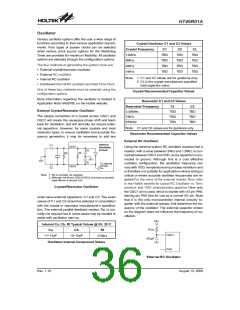
Crystal Oscillator C1 and C2 Values
Crystal Frequency
12MHz
C1
C2
CL
TBD
TBD
TBD
TBD
TBD
TBD
TBD
TBD
TBD
TBD
TBD
TBD
8MHz
The four methods of generating the system clock are:
4MHz
·
·
·
·
External crystal/resonator oscillator
External RC oscillator
1MHz
Note: 1. C1 and C2 values are for guidance only.
2. CL is the crystal manufacturer specified
load capacitor value.
Internal RC oscillator
Combined Internal RC oscillator and Real Time Clock
One of these four methods must be selected using the
configuration options.
Crystal Recommended Capacitor Values
More information regarding the oscillator is located in
Application Note HA0075E on the Holtek website.
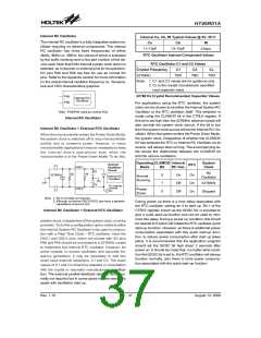
Resonator C1 and C2 Values
Resonator Frequency
3.58MHz
C1
C2
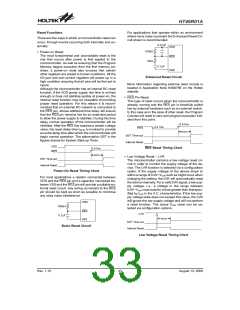
External Crystal/Resonator Oscillator
TBD
TBD
TBD
TBD
TBD
TBD
The simple connection of a crystal across OSC1 and
OSC2 will create the necessary phase shift and feed-
back for oscillation, and will normally not require exter-
nal capacitors. However, for some crystals and most
resonator types, to ensure oscillation and accurate fre-
quency generation, it may be necessary to add two
1MHz
455kHz
Note: C1 and C2 values are for guidance only.
Resonator Recommended Capacitor Values
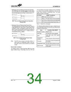
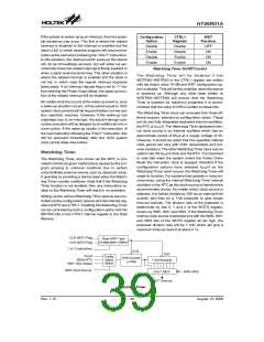
External RC Oscillator
I
n
t
e
r
n
a
l
C
1
O
S
C
1
Using the external system RC oscillator requires that a
resistor, with a value between 24kW and 1.5MW, is con-
nected between OSC1 and VDD, and a capacitor is con-
nected to ground. Although this is a cost effective
oscillator configuration, the oscillation frequency can
vary with VDD, temperature and process variations and
is therefore not suitable for applications where timing is
critical or where accurate oscillator frequencies are re-
quired.For the value of the external resistor ROSC refer
to the Holtek website for typical RC Oscillator vs. Tem-
perature and VDD characteristics graphics Here only
the OSC1 pin is used, which is shared with I/O pin PA6,
leaving pin PA5 free for use as a normal I/O pin. Note
that it is the only microcontroller internal circuitry to-
gether with the external resistor, that determine the fre-
quency of the oscillator. The external capacitor shown
on the diagram does not influence the frequency of os-
cillation.
O
C
s
c
i
l
l
a
t
o
r
i
r
c
u
i
t
C
a
R
p
R
f
C
b
T
o
i
n
t
e
r
n
a
l
c
i
r
c
u
i
t
s
O
S
C
2
C
2
N
o
t
e
:
1
.
R
A
c
p
i
s
n
o
r
m
a
l
l
y
n
o
t
r
e
q
u
i
r
e
d
.
2
.
l
t
h
o
u
g
h
n
o
t
s
h
o
w
n
O
S
C
1
/
O
S
C
2
p
i
n
s
h
a
v
e
a
p
a
r
a
s
i
t
i
c
a
p
a
c
i
t
a
n
c
e
o
f
a
r
o
u
n
d
7
p
F
.
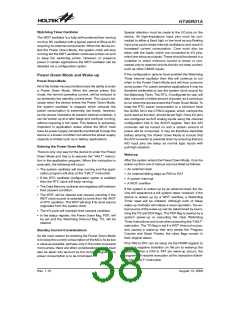
Crystal/Resonator Oscillator
small value external capacitors, C1 and C2. The exact
values of C1 and C2 should be selected in consultation
with the crystal or resonator manufacturer¢s specifica-
tion. The external parallel feedback resistor, Rp, is nor-
mally not required but in some cases may be needed to
assist with oscillation start up.
V
D
D
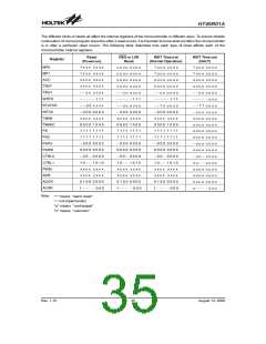
Internal Ca, Cb, Rf Typical Values @ 5V, 25°C
R
O
S
C
Ca
Cb
Rf
O
S
C
1
11~13pF
13~15pF
270kW
4
7
0
p
F
Oscillator Internal Component Values
P
A
5
External RC Oscillator
Rev. 1.10
36
August 13, 2008

 HOLTIC [ HOLT INTEGRATED CIRCUITS ]