HT46R01A
If the system is woken up by an interrupt, then two possi-
ble situations may occur. The first is where the related
interrupt is disabled or the interrupt is enabled but the
stack is full, in which case the program will resume exe-
cution at the instruction following the ²HALT² instruction.
In this situation, the interrupt which woke-up the device
will not be immediately serviced, but will rather be ser-
viced later when the related interrupt is finally enabled or
when a stack level becomes free. The other situation is
where the related interrupt is enabled and the stack is
not full, in which case the regular interrupt response
takes place. If an interrupt request flag is set to ²1² be-
fore entering the Power Down Mode, the wake-up func-
tion of the related interrupt will be disabled.
Configuration
Option
CTRL1
WDT
Register
Function
Disable
Enable
Disable
Enable
Disable
Disable
Enable
Enable
OFF
ON
ON
ON
Watchdog Timer On/Off Control
The Watchdog Timer will be disabled if bits
WDTEN3~WDTEN0 in the CTRL1 register are written
with the binary value 1010B and WDT configuration op-
tion is disable. This will be the condition when the device
is powered up. Although any other data written to
WDTEN3~WDTEN0 will ensure that the Watchdog
Timer is enabled, for maximum protection it is recom-
mended that the value 0101B is written to these bits.
No matter what the source of the wake-up event is, once
a wake-up situation occurs, a time period equal to 1024
system clock periods will be required before normal sys-
tem operation resumes. However, if the wake-up has
originated due to an interrupt, the actual interrupt sub-
routine execution will be delayed by an additional one or
more cycles. If the wake-up results in the execution of
the next instruction following the ²HALT² instruction, this
will be executed immediately after the 1024 system
clock period delay has ended.
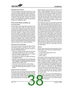
The Watchdog Timer clock can emanate from three dif-
ferent sources, selected by configuration option. These
are its own fully integrated dedicated internal oscillator,
the RTC or fSYS/4. The Watchdog Timer dedicated inter-
nal clock source is an internal oscillator which has an
approximate period of 65ms at a supply voltage of 5V.
However, it should be noted that this specified internal
clock period can vary with VDD, temperature and pro-
cess variations. The other Watchdog Timer clock source
options are the fSYS/4 clock and the RTC. It is important
to note that when the system enters the Power Down
Mode the instruction clock is stopped, therefore if the
configuration options have selected fSYS/4 as the
Watchdog Timer clock source, the Watchdog Timer will
cease to function. For systems that operate in noisy en-
vironments, using the internal Watchdog Timer internal
oscillator or the RTC as the clock source is therefore the
recommended choice. No matter which clock source is
selected, it is further divided by 256 via an internal 8-bit
counter and then by a 7-bit prescaler to give longer
time-out periods. The division ratio of the prescaler is
determined by bits 0, 1 and 2 of the WDTS register,
known as WS0, WS1 and WS2. If the Watchdog Timer
internal clock source is selected and with the WS0, WS1
and WS2 bits of the WDTS register all set high, the
prescaler division ratio will be 1:128, which will give a
maximum time-out period of about 2.1s.
Watchdog Timer
The Watchdog Timer, also known as the WDT, is pro-
vided to inhibit program malfunctions caused by the pro-
gram jumping to unknown locations due to certain
uncontrollable external events such as electrical noise.
It operates by providing a device reset when the Watch-
dog Timer counter overflows. Note that if the Watchdog
Timer function is not enabled, then any instructions re-
lated to the Watchdog Timer will result in no operation.
Setting up the various Watchdog Timer options are con-
trolled via the configuration options and two internal reg-
isters WDTS and CTRL1. Enabling the Watchdog Timer
can be controlled by both a configuration option and the
WDTEN bits in the CTRL1 internal register in the Data
Memory.
C
C
L
L
R
R
W
W
D
D
T
T
1
2
F
F
l
l
a
a
g
g
C
l
e
a
r
W
D
T
T
y
p
e
C
o
n
f
i
g
u
r
a
t
i
o
n
O
p
t
i
o
n
1
o
r
2
I
n
s
t
r
u
c
t
i
o
n
s
C
L
R
C
L
R
f
S
Y
S
/
4
C
o
n
f
i
g
.
8
-
b
i
t
C
o
u
n
t
e
r
3
2
k
H
z
R
T
C
O
p
t
i
o
n
7
-
b
i
t
P
r
e
s
c
a
l
e
r
(
¸
2 5 6 )
W
D
T
O
S
C
O
u
t
r
p
u
t
S
e
l
e
c
t
W
D
T
C
l
o
c
k
S
o
u
c
e
8
-
t
o
-
1
M
U
X
W
S
0
~
W
S
2
W
D
T
T
i
m
e
-
o
u
t
Watchdog Timer
Rev. 1.10
39
August 13, 2008

 HOLTIC [ HOLT INTEGRATED CIRCUITS ]