HT46R01A
Watchdog Timer Oscillator
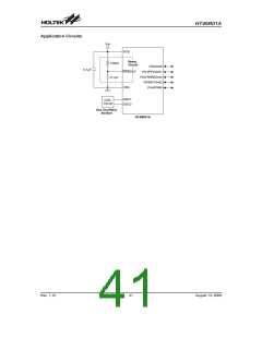
Special attention must be made to the I/O pins on the
device. All high-impedance input pins must be con-
nected to either a fixed high or low level as any floating
input pins could create internal oscillations and result in
increased current consumption. Care must also be
taken with the loads, which are connected to I/O pins,
which are setup as outputs. These should be placed in a
condition in which minimum current is drawn or con-
nected only to external circuits that do not draw current,
such as other CMOS inputs.
The WDT oscillator is a fully self-contained free running
on-chip RC oscillator with a typical period of 65ms at 5V
requiring no external components. When the device en-
ters the Power Down Mode, the system clock will stop
running but the WDT oscillator continues to free-run and
to keep the watchdog active. However, to preserve
power in certain applications the WDT oscillator can be
disabled via a configuration option.
If the configuration options have enabled the Watchdog
Timer internal oscillator then this will continue to run
when in the Power Down Mode and will thus consume
some power. For power sensitive applications it may be
therefore preferable to use the system clock source for
the Watchdog Timer. The RTC, if configured for use, will
also consume a limited amount of power, as it continues
to run when the device enters the Power Down Mode. To
keep the RTC power consumption to a minimum level
the QOSC bit in the CTRL0 register, which controls the
quick start up function, should be set high. If any I/O pins
are configured as A/D analog inputs using the channel
configuration bits in the ADCR register, then the A/D
converter will be turned on and a certain amount of
power will be consumed. It may be therefore desirable
before entering the Power Down Mode to ensure that
the A/D converter is powered down by ensuring that any
A/D input pins are setup as normal logic inputs with
pull-high resistors.
Power Down Mode and Wake-up
Power Down Mode
All of the Holtek microcontrollers have the ability to enter
a Power Down Mode. When the device enters this
mode, the normal operating current, will be reduced to
an extremely low standby current level. This occurs be-
cause when the device enters the Power Down Mode,
the system oscillator is stopped which reduces the
power consumption to extremely low levels, however,
as the device maintains its present internal condition, it
can be woken up at a later stage and continue running,
without requiring a full reset. This feature is extremely
important in application areas where the MCU must
have its power supply constantly maintained to keep the
device in a known condition but where the power supply
capacity is limited such as in battery applications.
Entering the Power Down Mode
There is only one way for the device to enter the Power
Down Mode and that is to execute the ²HALT² instruc-
tion in the application program. When this instruction is
executed, the following will occur:
Wake-up
After the system enters the Power Down Mode, it can be
woken up from one of various sources listed as follows:
·
·
·
·
·
·
·
·
An external reset
The system oscillator will stop running and the appli-
cation program will stop at the ²HALT² instruction.
An external falling edge on PA0 to PA7
A system interrupt
If the RTC oscillator configuration option is enabled
then the RTC clock will keep running.
A WDT overflow
The Data Memory contents and registers will maintain
their present condition.
If the system is woken up by an external reset, the de-
vice will experience a full system reset, however, if the
device is woken up by a WDT overflow, a Watchdog
Timer reset will be initiated. Although both of these
wake-up methods will initiate a reset operation, the ac-
tual source of the wake-up can be determined by exam-
ining the TO and PDF flags. The PDF flag is cleared by a
system power-up or executing the clear Watchdog
Timer instructions and is set when executing the ²HALT²
instruction. The TO flag is set if a WDT time-out occurs,
and causes a wake-up that only resets the Program
Counter and Stack Pointer, the other flags remain in
their original status.
The WDT will be cleared and resume counting if the
WDT clock source is selected to come from the WDT
or RTC oscillator. The WDT will stop if its clock source
originates from the system clock.
·
·
The I/O ports will maintain their present condition.
In the status register, the Power Down flag, PDF, will
be set and the Watchdog time-out flag, TO, will be
cleared.
Standby Current Considerations
As the main reason for entering the Power Down Mode
is to keep the current consumption of the MCU to as low
a value as possible, perhaps only in the order of several
micro-amps, there are other considerations which must
also be taken into account by the circuit designer if the
power consumption is to be minimised.
Pins PA0 to PA7 can be setup via the PAWK register to
permit a negative transition on the pin to wake-up the
system. When a PA0 to PA7 pin wake-up occurs, the
program will resume execution at the instruction follow-
ing the ²HALT² instruction.
Rev. 1.10
38
August 13, 2008

 HOLTIC [ HOLT INTEGRATED CIRCUITS ]