HT46R01A
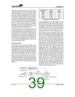
Under normal program operation, a Watchdog Timer
time-out will initialise a device reset and set the status bit
TO. However, if the system is in the Power Down Mode,
when a Watchdog Timer time-out occurs, the device will
be woken up, the TO bit in the status register will be set
and only the Program Counter and Stack Pointer will be
reset. Three methods can be adopted to clear the con-
tents of the Watchdog Timer. The first is an external
hardware reset, which means a low level on the external
reset pin, the second is using the Clear Watchdog Timer
software instructions and the third is when a HALT in-
struction is executed. There are two methods of using
software instructions to clear the Watchdog Timer, one
of which must be chosen by configuration option. The
first option is to use the single ²CLR WDT² instruction
while the second is to use the two commands ²CLR
WDT1² and ²CLR WDT2². For the first option, a simple
execution of ²CLR WDT² will clear the Watchdog Timer
while for the second option, both ²CLR WDT1² and
²CLR WDT2² must both be executed to successfully
clear the Watchdog Timer. Note that for this second op-
tion, if ²CLR WDT1² is used to clear the Watchdog
Timer, successive executions of this instruction will
have no effect, only the execution of a ²CLR WDT2² in-
struction will clear the Watchdog Timer. Similarly after
the ²CLR WDT2² instruction has been executed, only a
successive ²CLR WDT1² instruction can clear the
Watchdog Timer.
b
7
b
0
I
N
T
E
S
1
I
N
T
E
S
0
W D T E N 3 W D T E N 2 W D T E N 1 W D T E N 0
C
T
R
L
1
R
e
g
i
s
t
e
r
W
a
t
c
h
d
o
g
T
i
m
e
r
F
u
n
c
t
i
o
n
1
0
1
0
D
E
i
s
a
b
l
e
e
0
1
0
1
n
a
b
l
-
r
e
c
o
m
-
m
e
n
d
e
d
v
a
l
u
e
X
X
X
X
O
t
h
e
r
v
a
l
u
e
s
a
l
l
e
n
a
b
l
e
b
7
b
0
W
S
2
W
S
1
W
S
0
W
D
T
S
R
e
g
i
s
t
e
r
W
D
T
p
r
e
s
c
a
l
e
r
r
a
t
e
s
e
l
e
c
t
W
S
2
W
S
1
W
S
0
W
D
T
R
a
t
e
0
0
0
0
1
1
1
1
0
0
1
1
0
0
1
1
0
1
0
1
0
1
0
1
1
:
1
1
:
2
1
:
4
1
:
8
1
1
1
1
:
:
:
:
1
3
6
1
6
2
4
2
8
N
o
t
u
s
e
d
Configuration Options
Configuration options refer to certain options within the MCU that are programmed into the OTP Program Memory de-
vice during the programming process. During the development process, these options are selected using the HT-IDE
software development tools. As these options are programmed into the device using the hardware programming tools,
once they are selected they cannot be changed later by the application software. All options must be defined for proper
system function, the details of which are shown in the table.
No.
1
Options
Watchdog Timer: enable or disable
2
Watchdog Timer clock source: WDT internal oscillator, fSYS/4 or RTC
CLRWDT instructions: 1 or 2 instructions
3
4
System oscillator: Internal RC, Internal RC with external RTC, External Crystal, External RC
LVR function: enable or disable
5
6
LVR voltage: 2.1V, 3.15V or 4.2V
7
RES or PA7
8
SST: enable (1024 clocks) or disable (2 clocks)
Rev. 1.10
40
August 13, 2008

 HOLTIC [ HOLT INTEGRATED CIRCUITS ]