HT46R01A
The external interrupt pin is pin-shared with the I/O pin
PA3 and can only be configured as an external interrupt
pin if the corresponding external interrupt enable bit in
the INTC0 register has been set and the edge trigger
type has been selected using the CTRL1 register. The
pin must also be setup as an input by setting the corre-
sponding PAC.3 bit in the port control register. When the
interrupt is enabled, the stack is not full and a transition
appears on the external interrupt pin, a subroutine call to
the external interrupt vector at location 04H, will take
place. When the interrupt is serviced, the external inter-
rupt request flag, EIF, will be automatically reset and the
EMI bit will be automatically cleared to disable other in-
terrupts. Note that any pull-high resistor connections on
this pin will remain valid even if the pin is used as an ex-
ternal interrupt input.
It is recommended that programs do not use the ²CALL
subroutine² instruction within the interrupt subroutine.
Interrupts often occur in an unpredictable manner or
need to be serviced immediately in some applications. If
only one stack is left and the interrupt is not well con-
trolled, the original control sequence will be damaged
once a ²CALL subroutine² is executed in the interrupt
subroutine.
All of these interrupts have the capability of waking up
the processor when in the Power Down Mode.
Only the Program Counter is pushed onto the stack. If
the contents of the register or status register are altered
by the interrupt service program, which may corrupt the
desired control sequence, then the contents should be
saved in advance.
Timer/Event Counter Interrupt
Reset and Initialisation
For a Timer/Event Counter interrupt to occur, the global
interrupt enable bit, EMI, and the corresponding timer
interrupt enable bit, ET0I, must first be set. An actual
Timer/Event Counter interrupt will take place when the
Timer/Event Counter request flag, T0F, is set, a situation
that will occur when the Timer/Event Counter overflows.
When the interrupt is enabled, the stack is not full and a
Timer/Event Counter overflow occurs, a subroutine call
to the timer interrupt vector at location 08H, will take
place. When the interrupt is serviced, the timer interrupt
request flag, T0F, will be automatically reset and the
EMI bit will be automatically cleared to disable other in-
terrupts.
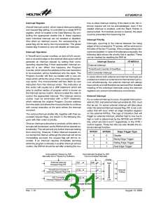
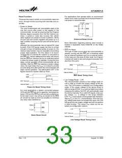
A reset function is a fundamental part of any
microcontroller ensuring that the device can be set to
some predetermined condition irrespective of outside
parameters. The most important reset condition is after
power is first applied to the microcontroller. In this case,
internal circuitry will ensure that the microcontroller, af-
ter a short delay, will be in a well defined state and ready
to execute the first program instruction. After this
power-on reset, certain important internal registers will
be set to defined states before the program com-
mences. One of these registers is the Program Counter,
which will be reset to zero forcing the microcontroller to
begin program execution from the lowest Program
Memory address.
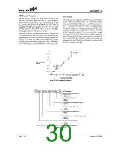
A/D Interrupt
In addition to the power-on reset, situations may arise
where it is necessary to forcefully apply a reset condition
when the microcontroller is running. One example of this
is where after power has been applied and the
microcontroller is already running, the RES line is force-
fully pulled low. In such a case, known as a normal oper-
ation reset, some of the microcontroller registers remain
unchanged allowing the microcontroller to proceed with
normal operation after the reset line is allowed to return
high. Another type of reset is when the Watchdog Timer
overflows and resets the microcontroller. All types of re-
set operations result in different register conditions be-
ing setup.
For an A/D interrupt to occur, the global interrupt enable
bit, EMI, and the corresponding interrupt enable bit,
EADI, must be first set. An actual A/D interrupt will take
place when the A/D converter request flag, ADF, is set, a
situation that will occur when an A/D conversion process
has completed. When the interrupt is enabled, the stack
is not full and an A/D conversion process finishes exe-
cution, a subroutine call to the A/D interrupt vector at lo-
cation 0CH, will take place. When the interrupt is
serviced, the A/D interrupt request flag, ADF, will be au-
tomatically reset and the EMI bit will be automatically
cleared to disable other interrupts.
Programming Considerations
Another reset exists in the form of a Low Voltage Reset,
LVR, where a full reset, similar to the RES reset is imple-
mented in situations where the power supply voltage
falls below a certain threshold.
By disabling the interrupt enable bits, a requested inter-
rupt can be prevented from being serviced, however,
once an interrupt request flag is set, it will remain in this
condition in the interrupt register until the corresponding
interrupt is serviced or until the request flag is cleared by
a software instruction.
Rev. 1.10
32
August 13, 2008

 HOLTIC [ HOLT INTEGRATED CIRCUITS ]