HT46R01A
·
Watchdog Time-out Reset during Normal Operation
The Watchdog time-out Reset during normal opera-
tion is the same as a hardware RES pin reset except
that the Watchdog time-out flag TO will be set to ²1².
TO are located in the status register and are controlled
by various microcontroller operations, such as the
Power Down function or Watchdog Timer. The reset
flags are shown in the table:
W
D
T
T
i
m
e
-
o
u
t
TO PDF
RESET Conditions
t
R S T D
0
u
1
1
0
u
u
1
RES reset during power-on
S
S
T
T
i
m
e
-
o
u
t
RES or LVR reset during normal operation
WDT time-out reset during normal operation
WDT time-out reset during Power Down
I
n
t
e
r
n
a
l
R
e
s
e
t
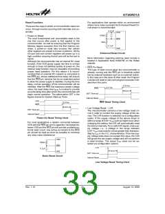
WDT Time-out Reset during Normal Operation
Timing Chart
Note: ²u² stands for unchanged
·
Watchdog Time-out Reset during Power Down
The Watchdog time-out Reset during Power Down is
a little different from other kinds of reset. Most of the
conditions remain unchanged except that the Pro-
gram Counter and the Stack Pointer will be cleared to
²0² and the TO flag will be set to ²1². Refer to the A.C.
Characteristics for tSST details.
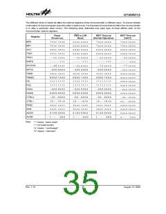
The following table indicates the way in which the vari-
ous components of the microcontroller are affected after
a power-on reset occurs.
Item
Condition After RESET
Program Counter Reset to zero
Interrupts
WDT
All interrupts will be disabled
W
D
T
T
i
m
e
-
o
u
t
t
S
S
T
Clear after reset, WDT begins
counting
S
S
T
T
i
m
e
-
o
u
t
WDT Time-out Reset during Power Down
Timing Chart
Timer/Event
Counter
Timer Counter will be turned off
The Timer Counter Prescaler will
be cleared
Note:
The SST can be chosen to be either 1024 or 2
clock cycles via configuration option if the sys-
tem clock source is not provided by an external
crystal
Prescaler
Input/Output Ports I/O ports will be setup as inputs
Stack Pointer will point to the top
Stack Pointer
of the stack
Reset Initial Conditions
The different types of reset described affect the reset
flags in different ways. These flags, known as PDF and
Rev. 1.10
34
August 13, 2008

 HOLTIC [ HOLT INTEGRATED CIRCUITS ]