HT46R01A
Internal RC Oscillator
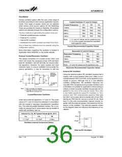
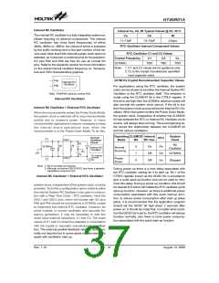
Internal Ca, Cb, Rf Typical Values @ 5V, 25°C
The internal RC oscillator is a fully integrated system os-
cillator requiring no external components. The internal
RC oscillator has three fixed frequencies of either
4MHz, 8MHz or 12MHz, the choice of which is indicated
by the suffix marking next to the part number of the de-
vice used. Note that if this internal system clock option is
selected, as it requires no external pins for its operation,
I/O pins PA5 and PA6 are free for use as normal I/O
pins. Refer to the Appendix section for more information
on the actual internal oscillator frequency vs. Tempera-
ture and VDD characteristics graphics.
Ca
Cb
Rf
11~13pF
13~15pF
270kW
RTC Oscillator Internal Component Values
RTC Oscillator C1 and C2 Values
Crystal Frequency
C1
C2
CL
32768Hz
TBD
TBD
TBD
Note: 1. C1 and C2 values are for guidance only.
2. CL is the crystal manufacturer specified
load capacitor value.
P
P
A
A
5
6
32768 Hz Crystal Recommended Capacitor Values
I
n
t
e
r
n
a
l
R
C
O
s
c
i
l
l
a
t
o
r
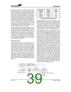
For applications using the RTC oscillator, the system
clock can be chosen to be either the Internal System RC
Oscillator or the RTC oscillator itself. This selection is
made using the CLKMOD bit in the CTRL0 register. If
this bit is set high then the 32768Hz external crystal will
also provide the system clock source. If the bit is low
then the system clock source will be the Internal RC Os-
cillator. When the system enters the Power Down Mode,
the system clock, irrespective of whether the CLKMOD
bit has selected the RTC or Internal RC Oscillator as its
source, will always stop running. The accompanying ta-
ble shows the relationship between the CLKMOD bit
and the various oscillators.
N
o
t
e
:
Internal RC Oscillator
Internal RC Oscillator + External RTC Oscillator
When the microcontroller enters the Power Down Mode,
the system clock is switched off to stop microcontroller
activity and to conserve power. However, in many
microcontroller applications it may be necessary to keep
the internal timers operational even when the
microcontroller is in the Power Down Mode. To do this,
Operating CLKMOD Internal
System
Clock
I
O
C
n
t
e
r
n
a
l
RTC
C
1
Mode
Bit
RC Osc.
O
S
C
1
s
c
i
l
l
a
t
o
r
i
r
c
u
i
t
C
a
RC
R
p
R
f
3
2
7
6
8
H
z
0
On
On
On
On
Normal
I
n
t
e
r
n
a
l
R
C
Oscillator
O
s
c
i
l
l
a
t
o
r
Running
1
Off
32768Hz
Stopped
C
b
T
c
o
i
n
t
e
r
n
a
l
i
r
c
u
i
t
s
O
S
C
2
Power
Down
C
2
X
Off
N
o
t
e
:
1
.
R
A
c
p
i
s
n
o
r
m
a
l
l
y
n
o
t
r
e
q
u
i
r
e
d
.
2
.
l
t
h
o
u
g
h
n
o
t
s
h
o
w
n
O
S
C
1
/
O
S
C
2
p
i
n
s
h
a
v
e
a
p
a
r
a
s
i
t
i
c
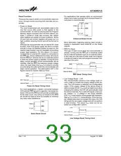
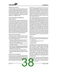
During power up there is a time delay associated with
the RTC oscillator waiting for it to start up. Bit 1 of the
CTRL0 register, known as the QOSC bit, is provided to
give a quick start-up function and can be used to mini-
mize this delay. During a power up condition, this bit will
be cleared to 0 which will initiate the RTC oscillator quick
start-up function. However, as there is additional power
consumption associated with this quick start-up func-
tion, to reduce power consumption after start up takes
place, it is recommended that the application program
should set the QOSC bit high about 2 seconds after
power on. It should be noted that, no matter what condi-
tion the QOSC bit is set to, the RTC oscillator will always
function normally, only there is more power consump-
tion associated with the quick start-up function.
a
p
a
c
i
t
a
n
c
e
o
f
a
r
o
u
n
d
7
p
F
.
Internal RC Oscillator + External RTC Oscillator
another clock, independent of the system clock, must be
provided. To do this a configuration option exists to allow
the Internal System RC Oscillator to be used in conjunc-
tion with a Real Time Clock - RTC oscillator. Here the
OSC1 and OSC2 pins, which are shared with I/O pins
PA6 and PA5 should be connected to a 32768Hz crystal
to implement this internal RTC oscillator. However, for
some crystals, to ensure oscillation and accurate fre-
quency generation, it may be necessary to add two
small value external capacitors, C1 and C2. The exact
values of C1 and C2 should be selected in consultation
with the crystal or resonator manufacturer¢s specifica-
tion. The external parallel feedback resistor, Rp, is nor-
mally not required but in some cases may be needed to
assist with oscillation start up.
Rev. 1.10
37
August 13, 2008

 HOLTIC [ HOLT INTEGRATED CIRCUITS ]