Preliminary
HT48R06A-1
Functional Description
When executing a jump instruction, conditional
skip execution, loading PCL register, subrou-
tine call, initial reset, internal interrupt, exter-
nal interrupt or return from subroutine, the PC
manipulates the program transfer by loading
the address corresponding to each instruction.
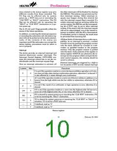
Execution flow
The system clock for the microcontroller is de-
rived from either a crystal or an RC oscillator.
The system clock is internally divided into four
non-overlapping clocks. One instruction cycle
consists of four system clock cycles.
The conditional skip is activated by instruc-
tions. Once the condition is met, the next in-
struction, fetched during the current
instruction execution, is discarded and a
dummy cycle replaces it to get the proper in-
struction. Otherwise proceed with the next in-
struction.
Instruction fetching and execution are
pipelined in such a way that a fetch takes an in-
struction cycle while decoding and execution
takes the next instruction cycle. However, the
pipelining scheme causes each instruction to ef-
fectively execute in a cycle. If an instruction
changes the program counter, two cycles are re-
quired to complete the instruction.
The lower byte of the program counter (PCL) is
a readable and writable register (06H). Moving
data into the PCL performs a short jump. The
destination will be within 256 locations.
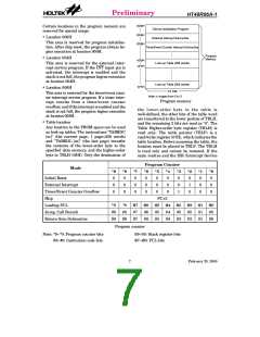
Program counter - PC
The program counter (PC) controls the se-
quence in which the instructions stored in pro-
gram PROM are executed and its contents
specify full range of program memory.
When a control transfer takes place, an addi-
tional dummy cycle is required.
Program memory - PROM
After accessing a program memory word to fetch
an instruction code, the contents of the program
counter are incremented by one. The program
counter then points to the memory word contain-
ing the next instruction code.
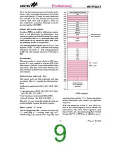
The program memory is used to store the pro-
gram instructions which are to be executed. It
also contains data, table, and interrupt entries,
and is organized into 1024´14 bits, addressed
by the program counter and table pointer.
T
1
T
2
T
3
T
1
T
4
T
2
T
3
T
1
T
4
T
2
T
3
T
4
S
y
s
t
e
m
C
l
o
c
k
O
S
C
2
(
R
C
o
n
l
y
)
P
C
P
C
+
1
P
C
+
2
P
C
F
E
e
t
e
c
h
I
N
S
T
(
P
C
)
x
c
u
t
e
I
N
S
T
(
P
C
-
1
)
S T
F
E
e
t
e
c
h
I
N
(
P
C
+
1
)
x
c
u
t
e
I
N
S
T
(
P
C
)
N
F
E
e
t
e
c
h
I
S
T
(
P
C
+
2
)
x
c
u
t
e
I
N
S
T
(
P
C
+
1
)
Execution flow
6
February 25, 2000

 HOLTEK [ HOLTEK SEMICONDUCTOR INC ]