HT46R064G/065G/0662G
Enhanced A/D Type 8-Bit OTP MCU with OPA
Using this method of frequency generation, and if a crystal oscillator is used for the system clock, very
precise values of frequency can be generated.
T
i
m
e
r
O
v
e
r
f
l
o
w
P
F
D
C
l
o
c
k
I
/
O
P
i
n
D
a
t
a
P
F
D
O
u
t
p
u
t
a
t
I
/
O
P
i
n
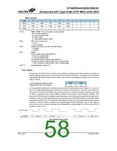
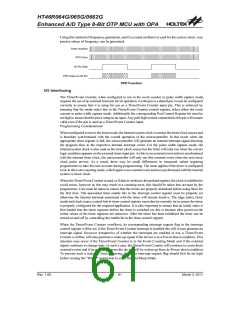
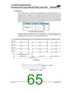
PFD Function
I/O Interfacing
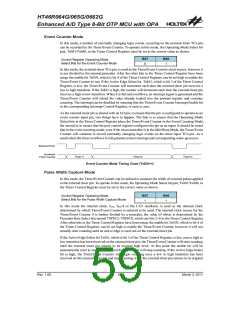
The Timer/Event Counter, when configured to run in the event counter or pulse width capture mode,
requires the use of an external timer pin for its operation. As this pin is a shared pin it must be configured
correctly to ensure that it is setup for use as a Timer/Event Counter input pin. This is achieved by
ensuring that the mode select bits in the Timer/Event Counter control register, select either the event
counter or pulse width capture mode. Additionally the corresponding Port Control Register bit must be
set high to ensure that the pin is setup as an input. Any pull-high resistor connected to this pin will remain
valid even if the pin is used as a Timer/Event Counter input.
Programming Considerations
When configured to run in the timer mode, the internal system clock is used as the timer clock source and
is therefore synchronised with the overall operation of the microcontroller. In this mode when the
appropriate timer register is full, the microcontroller will generate an internal interrupt signal directing
the program flow to the respective internal interrupt vector. For the pulse width capture mode, the
internal system clock is also used as the timer clock source but the timer will only run when the correct
logic condition appears on the external timer input pin. As this is an external event and not synchronised
with the internal timer clock, the microcontroller will only see this external event when the next timer
clock pulse arrives. As a result, there may be small differences in measured values requiring
programmers to take this into account during programming. The same applies if the timer is configured
to be in the event counting mode, which again is an external event and not synchronised with the internal
system or timer clock.
When the Timer/Event Counter is read, or if data is written to the preload register, the clock is inhibited to
avoid errors, however as this may result in a counting error, this should be taken into account by the
programmer. Care must be taken to ensure that the timers are properly initialised before using them for
the first time. The associated timer enable bits in the interrupt control register must be properly set
otherwise the internal interrupt associated with the timer will remain inactive. The edge select, timer
mode and clock source control bits in timer control register must also be correctly set to ensure the timer
is properly configured for the required application. It is also important to ensure that an initial value is
first loaded into the timer registers before the timer is switched on; this is because after power-on the
initial values of the timer registers are unknown. After the timer has been initialised the timer can be
turned on and off by controlling the enable bit in the timer control register.
When the Timer/Event Counter overflows, its corresponding interrupt request flag in the interrupt
control register will be set. If the Timer/Event Counter interrupt is enabled this will in turn generate an
interrupt signal. However irrespective of whether the interrupts are enabled or not, a Timer/Event
Counter overflow will also generate a wake-up signal if the device is in a Power-down condition. This
situation may occur if the Timer/Event Counter is in the Event Counting Mode and if the external
signal continues to change state. In such a case, the Timer/Event Counter will continue to count these
external events and if an overflow occurs the device will be woken up from its Power-down condition.
To prevent such a wake-up from occurring, the timer interrupt request flag should first be set high
before issuing the ²HALT² instruction to enter the Idle/Sleep Mode.
Rev. 1.00
61
March 3, 2011

 HOLTEK [ HOLTEK SEMICONDUCTOR INC ]