HT46R064G/065G/0662G
Enhanced A/D Type 8-Bit OTP MCU with OPA
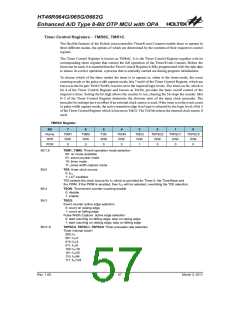
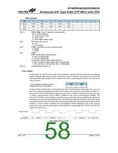
TMR1C Register
Bit
7
T1M1
R/W
0
6
T1M0
R/W
0
5
4
T1ON
R/W
0
3
T1EG
R/W
1
2
1
0
Name
R/W
T1S
R/W
0
¾
¾
¾
¾
¾
¾
¾
¾
¾
POR
Bit 7,6
T1M1, T1M0: Timer 1 Operation mode selection
00: no mode available
01: event counter mode
10: timer mode
11: pulse width capture mode
Bit 5
Bit 4
T1S: timer clock source
0: fSYS/4
1: LXT oscillator
T1ON: Timer/event counter counting enable
0: disable
1: enable
Bit 3
T1EG:
Event counter active edge selection
0: count on raising edge
1: count on falling edge
Pulse Width Capture active edge selection
0: start counting on falling edge, stop on rasing edge
1: start counting on raising edge, stop on falling edge
Bit 2~0
unimplemented, read as ²0²
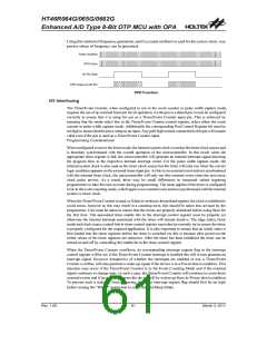
Timer Mode
In this mode, the Timer/Event Counter can be utilised to measure fixed time intervals, providing an
internal interrupt signal each time the Timer/Event Counter overflows. To operate in this mode, the
Operating Mode Select bit pair, TnM1/TnM0, in the Timer Control Register must be set to the correct
value as shown.
Bit7
Bit6
Control Register Operating Mode
Select Bits for the Timer Mode
1
0
In this mode the internal clock is used as the timer clock. The timer input clock source is fSYS, fSYS/4 or
the LXT oscillator depending upon whether the Timer/Event Counter 0 or Timer/Event Counter 1 is
selected. For Timer/Event Counter 0, the timer clock source is further divided by a prescaler, the value
of which is determined by the bits T0PSC2~T0PSC0 in the Timer Control Register TMR0C. The
timer-on bit, TnON must be set high to enable the timer to run. Each time an internal clock high to low
transition occurs, the timer increments by one; when the timer is full and overflows, an interrupt signal
is generated and the timer will reload the value already loaded into the preload register and continue
counting. A timer overflow condition and corresponding internal interrupt is one of the wake-up
sources, however, the internal interrupts can be disabled by ensuring that the TnE bits of the INTC0
register are reset to zero.
P
r
e
s
c
a
l
e
r
O
u
t
p
u
t
I
n
c
r
e
m
e
n
t
T
i
m
e
r
+
2
T
i
m
e
r
+
T
N
i
m
e
r
T
i m
r
e
r
+
1
T
i
m
e
r
C
o
u
n
t
e
Timer Mode Timing Chart
Rev. 1.00
58
March 3, 2011

 HOLTEK [ HOLTEK SEMICONDUCTOR INC ]