HT46RU66/HT46CU66
flag, RTF; bit 6 of the MFIC register, the time base inter-
rupt flag, TBF; bit 5 of the MFIC register, indicate that a
related interrupt has occurred. As these flags will not be
cleared automatically, they should be cleared by the
user. The enable control Timer 2 interrupt, ET2I, the en-
able time base interrupt, ETBI, the enable real time
clock interrupt, ERTI, constitute the Interrupt Control
Register 2, MFIC, which is located at 2FH in the Pro-
gram Memory.
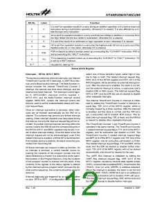
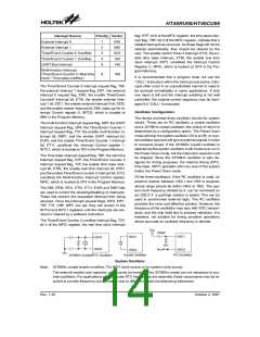
Interrupt Source
External Interrupt 0
Priority Vector
1
2
3
4
5
04H
08H
0CH
10H
14H
External Interrupt 1
Timer/Event Counter 0 Overflow
Timer/Event Counter 1 Overflow
UART Bus Interrupt
Multi-function Interrupt
(Timer/Event Counter 2 / Real time
clock / Time base overflow)
6
18H
It is recommended that a program does not use the
²CALL² instruction within the interrupt subroutine. Inter-
rupts often occur in an unpredictable manner or need to
be serviced immediately in some applications. If only
one stack is left and the interrupt enabling is not well
controlled, the original control sequence may be dam-
aged if a ²CALL² is executed.
The Timer/Event Counter 0 interrupt request flag, T0F,
the external interrupt 1 request flag, EIF1, the external
interrupt 0 request flag, EIF0, the enable Timer/Event
Counter0 interrupt bit, ET0I, the enable external inter-
rupt 1 bit, EEI1, the enable external interrupt 0 bit, EEI0,
and the enable master interrupt bit, EMI, make up the In-
terrupt Control register 0, INTC0, which is located at
0BH in the Program Memory.
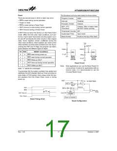
Oscillator Configuration
The device provides three oscillator circuits for system
clocks. These are an RC oscillator, a crystal oscillator
and a 32768Hz crystal oscillator, the choice of which is
determined by a configuration option. The Power Down
mode will stop the system oscillator, if it is an RC or crys-
tal oscillator type and will ignore external signals in order
to conserve power. If the 32768Hz crystal oscillator is
selected as the system oscillator, it will continue to run in
the Power Down mode, but the instruction execution will
be stopped. Since the 32768Hz oscillator is also de-
signed for timing purposes, the internal timing (RTC,
time base, WDT) operation still runs even if the system
enters the Power Down mode.
The multi-function interrupt request flag, MFF, the UART
interrupt request flag, URF, the Timer/Event Counter 1
interrupt request flag, T1F, the enable multi-function in-
terrupt bit, EMFI, and the enable UART interrupt bit,
EURI, and the enable Timer/Event Counter 1 interrupt
bit, ET1I, constitute the Interrupt Control register 1,
INTC1, which is located at 1EH in the Program Memory.
The Time base interrupt request flag, TBF, the real time
interrupt request flag, RTF, the Timer/Event Counter 2
interrupt request flag, T2F, the enable time base inter-
rupt bit, ETBI, the enable real time interrupt bit, ERTI,
and the enable Timer/Event counter 2 interrupt bit, ET2I,
constitute the Multi-function Interrupt Control register,
MFIC, which is located at 2FH in the Program Memory.
Of the three oscillators, if the RC oscillator is used, an
external resistor between OSC1 and VSS is required,
whose range should be within 24kW to 1MW. The sys-
tem clock frequency divided by 4, can be monitored on
pin OSC2 if a pull-high resistor is added. This can be
used to synchronise external logic. The RC oscillator
provides the most cost effective solution. However, the
frequency of the oscillation may vary with VDD, temper-
ature, and the chip itself due to process variations. It is
therefore, not suitable for timing sensitive operations
where accurate an oscillator frequency is desired.
The EMI, EEI0, EEI1, ET0I, ET1I, EURI and EMFI bits
are used to control the enabling/disabling of interrupts.
These bits prevent the requested interrupt from being
serviced. Once the interrupt request flags, EIF0, EIF1,
T0F, T1F, URF, MFF, are set, they will remain in the
INTC0 and INTC1 registers until the interrupts are ser-
viced or cleared by a software instruction.
The Timer/Event Counter 2 overflow interrupt flag, T2F;
bit 4 of the MFIC register, the real time clock interrupt
V
D
D
4
7
0
p
F
O
S
C
1
O
S
C
1
O
S
C
3
O
S
C
4
S
Y
S
O
S
C
2
O
S
C
2
C
r
y
s
t
a
l
O
s
c
i
l
l
a
t
o
r
R
C
O
s
c
i
l
l
a
t
o
r
3
2
7
6
8
H
z
C
r
y
s
t
a
l
/
R
T
C
O
s
c
i
l
l
a
t
o
r
System Oscillator
Note: 32768Hz crystal enable condition: For WDT clock source or for system clock source.
The external resistor and capacitor components connected to the 32768Hz crystal are not necessary to pro-
vide oscillation. For applications where precise RTC frequencies are essential, these components may be re-
quired to provide frequency compensation due to different crystal manufacturing tolerances.
Rev. 1.20
14
October 2, 2007

 HOLTEK [ HOLTEK SEMICONDUCTOR INC ]