HT46RU66/HT46CU66
The Multi-Function Interrupt, MFI, is initialised by setting
the interrupt request flag, MFF; bit 6 of the INTC1 regis-
ter, that is caused by a Timer 2 overflow, T2F; bit 4 of the
MFIC register, caused by a regular real time clock
time-out, RTF; bit 6 of the MFIC register or caused by a
time base time-out, TBF; bit5 of the MFIC register. After
the interrupt is enabled, EMFI=1, the stack is not full,
and the MFF bit is set, a subroutine call to location 018H
will occur. The related interrupt request flag, MFF, is re-
set and the EMI bit is cleared to disable further
maskable interrupts. T2F, TBF and RTF indicate that a
related interrupt has occurred. As these flags will not be
cleared automatically after reading, they should be
cleared by the user.
During the execution of an interrupt subroutine, other
maskable interrupt acknowledgments are all held until
the ²RETI² instruction is executed or the EMI bit and the
related interrupt control bit are set both to 1, if the stack
is not full. To return from the interrupt subroutine, a
²RET² or ²RETI² instruction may be executed. RETI sets
the EMI bit and enables an interrupt service, but RET
does not.
Interrupts occurring in the interval between the rising
edges of two consecutive T2 pulses are serviced on the
latter of the two T2 pulses if the corresponding interrupts
are enabled. In the case of simultaneous requests, the
priorities in the following table apply. These can be
masked by resetting the EMI bit.
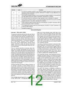
Bit No.
Label
EMI
Function
0
1
2
3
4
5
6
Controls the master (global) interrupt (1=enable; 0= disable)
EEI0
EEI1
ET0I
EIF0
EIF1
T0F
Controls the external interrupt 0 (1=enable; 0=disable)
Controls the external interrupt 1 (1=enable; 0=disable)
Controls the Timer/Event Counter 0 interrupt (1=enable; 0=disable)
External interrupt 0 request flag (1=active; 0=inactive)
External interrupt 1 request flag (1=active; 0=inactive)
Internal Timer/Event Counter 0 request flag (1=active; 0=inactive)
For test mode used only.
7
¾
Must be written as ²0²; otherwise may result in unpredictable operation.
INTC0 (0BH) Register
Bit No.
Label
ET1I
EURI
EMFI
¾
Function
Controls the Timer/Event Counter 1 interrupt (1=enable; 0=disable)
Control the UART Bus interrupt (1=enable; 0=disable)
Control the Multi-function interrupt (1=enable; 0=disable)
Unused bit, read as ²0²
0
1
2
3, 7
4
T1F
Internal Timer/Event Counter 1 request flag (1=active; 0=inactive)
UART Bus request flag (1=active; 0=inactive)
Multi-function interrupt request flag (1=active; 0=inactive)
INTC1 (1EH) Register
5
URF
MFF
6
Bit No.
Label
ET2I
ETBI
ERTI
¾
Function
0
1
Control the Timer/Event Counter 2 interrupt (1=enable; 0=disable)
Control the time base interrupt (1=enable; 0=disable)
Control the real time clock interrupt (1=enable; 0=disable)
Unused bit, read as ²0²
2
3, 7
4
T2F
Timer/Event Counter 2 interrupt request flag (1=active; 0=inactive)
Time base interrupt request flag (1=active; 0=inactive)
Real time clock interrupt request flag (1=active; 0=inactive)
5
TBF
RTF
6
MFIC (2FH) Register
Rev. 1.20
13
October 2, 2007

 HOLTEK [ HOLTEK SEMICONDUCTOR INC ]