HT46R64/HT46C64
In the event count or timer mode, the timer/event coun-
ter 0(1) starts counting at the current contents in the
timer/event counter 0(1) and ends at FFH(FFFFH).
Once an overflow occurs, the counter is reloaded from
the timer/event counter preload register, and generates
an interrupt request flag (T0F; bit 6 of INTC0, T1F; bit 4
of INTC1). In the pulse width measurement mode with
the values of the T0ON/T1ON and T0E/T1E bits equal
to 1, after the TMR0 (TMR1) has received a transient
from low to high (or high to low if the TE bit is ²0²), it will
start counting until the TMR0 (TMR1) returns to the orig-
inal level and resets the T0ON/T1ON. The measured re-
sult remains in the timer/event counter even if the
activated transient occurs again. In other words, only
1-cycle measurement can be made until the
T0ON/T1ON is set. The cycle measurement will
re-function as long as it receives further transient pulse.
In this operation mode, the timer/event counter begins
counting not according to the logic level but to the tran-
sient edges. In the case of counter overflows, the coun-
ter is reloaded from the timer/event counter register and
issues an interrupt request, as in the other two modes,
i.e., event and timer modes.
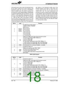
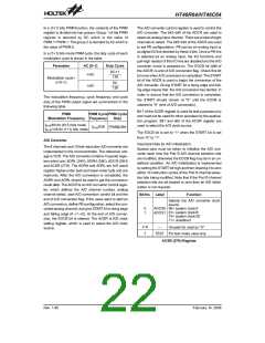
Bit No.
Label
Function
To define the prescaler stages.
T0PSC2, T0PSC1, T0PSC0=
000: fINT=fSYS
001: fINT=fSYS/2
0
1
2
T0PSC0
T0PSC1
T0PSC2
010: fINT=fSYS/4
011: fINT=fSYS/8
100: fINT=fSYS/16
101: fINT=fSYS/32
110: fINT=fSYS/64
111: fINT=fSYS/128
Defines the TMR0 active edge of the timer/event counter:
In Event Counter Mode (T0M1,T0M0)=(0,1):
1:count on falling edge;
3
T0E
0:count on rising edge
In Pulse Width measurement mode (T0M1,T0M0)=(1,1):
1: start counting on the rising edge, stop on the falling edge;
0: start counting on the falling edge, stop on the rising edge
4
5
T0ON
Enable/disable timer counting (0=disabled; 1=enabled)
¾
Unused bit, read as ²0²
Defines the operating mode T0M1, T0M0=
01=Event count mode (External clock)
10=Timer mode (Internal clock)
6
7
T0M0
T0M1
11=Pulse Width measurement mode (External clock)
00=Unused
TMR0C (0EH) Register
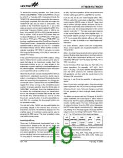
Bit No.
Label
Function
0~2
¾
Unused bit, read as ²0²
Defines the TMR1 active edge of the timer/event counter:
In Event Counter Mode (T1M1,T1M0)=(0,1):
1:count on falling edge;
3
T1E
0:count on rising edge
In Pulse Width measurement mode (T1M1,T1M0)=(1,1):
1: start counting on the rising edge, stop on the falling edge;
0: start counting on the falling edge, stop on the rising edge
4
5
T1ON
T1S
Enable/disable timer counting (0= disabled; 1= enabled)
Defines the TMR1 internal clock source (0=fSYS/4; 1=32768Hz)
Defines the operating mode T1M1, T1M0=
01=Event count mode (External clock)
10=Timer mode (Internal clock)
6
7
T1M0
T1M1
11=Pulse Width measurement mode (External clock)
00=Unused
TMR1C (11H) Register
Rev. 1.80
18
February 14, 2006
图片预览")
 HOLTEK [ HOLTEK SEMICONDUCTOR INC ]