HT46R51/HT46R52
The WDT time-out period is fixed to fs/216, because the
²CLR WDT² or ²CLR WDT1² and ²CLR WDT2²
instructions will clear the whole counter of the WDT.
To minimize power consumption, all the I/O pins should
be carefully managed before entering the HALT status.
Reset
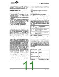
Power Down Operation - HALT
There are three ways in which a reset may occur:
·
·
·
RES reset during normal operation
RES reset during HALT
The HALT mode is initialized by the ²HALT² instruction
and results in the following...
·
The system oscillator is turned off but the WDT oscil-
lator keeps running (if the WDT oscillator or the real
time clock is selected).
WDT time-out reset during normal operation
The WDT time-out during HALT differs from other chip
reset conditions, for it can perform a ²warm reset² that
resets only the Program Counter and SP, leaving the
other circuits at their original state. Some registers re-
main unaffected during any other reset conditions. Most
registers are reset to the ²initial condition² when the re-
set conditions are met. Examining the PDF and TO
flags, the program can distinguish between different
²chip resets².
·
·
The contents of the on-chip RAM and registers remain
unchanged
The WDT and WDT prescaler will be cleared to zero. If
the WDT clock source is from the RTC/WDT oscilla-
tor, the WDT will remain active, and if the WDT clock
source is fSYS/4, the WDT will stop running.
All of the I/O ports maintain their original status
The PDF flag is set and the TO flag is cleared
·
·
The system quits the HALT mode by way of an external
reset, an interrupt, an external falling edge signal on port
A or a WDT overflow. An external reset causes a device
initialization and the WDT overflow performs a ²warm
reset². After examining the TO and PDF flags, the cause
for a chip reset can be determined. The PDF flag is
cleared by system power-up or by executing the ²CLR
WDT² instruction and is set when executing the ²HALT²
instruction. On the other hand, the TO flag is set if the
WDT time-out occurs, and causes a wake-up that only
resets the Program Counter and SP, and leaves the oth-
ers in their original status.
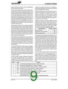
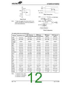
TO PDF
RESET Conditions
RES reset during power-up
RES reset during normal operation
RES wake-up HALT
0
u
0
1
1
0
u
1
u
1
WDT time-out during normal operation
WDT wake-up HALT
Note: ²u² stands for ²unchanged²
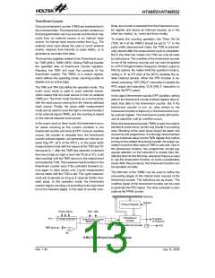
To guarantee that the system oscillator is started and
stabilized, the SST (System Start-up Timer) provides an
extra-delay of 1024 system clock pulses when the sys-
tem reset (power-up, WDT time-out or RES reset) or the
system awakes from the HALT state. When a system re-
set occurs, the SST delay is added during the reset pe-
riod. Any wake-up from the HALT will enable the SST
delay. An extra option load time delay is added during
system reset (Power-up, WDT time-out at normal mode
or RES reset).
The port A wake-up and interrupt methods can be con-
sidered as a continuation of normal execution. Each bit
in port A can be independently selected to wake-up the
device by options. Awakening from an I/O port stimulus,
the program resumes execution of the next instruction.
On the other hand, awakening from an interrupt, two se-
quence may occur. If the related interrupt is disabled or
the interrupt is enabled but the stack is full, the program
resumes execution at the next instruction. But if the in-
terrupt is enabled, and the stack is not full, the regular in-
terrupt response takes place. When an interrupt request
flag is set before entering the ²HALT² status, the system
cannot be awakened using that interrupt. If wake-up
events occur, it takes 1024 tSYS (system clock period) to
resume normal operation. In other words, a dummy pe-
riod is inserted after the wake-up. If the wake-up results
from an interrupt acknowledgment, the actual interrupt
subroutine execution is delayed by more than one cycle.
However, if the Wake-up results in the next instruction
execution, the execution will be performed immediately
after the dummy period is finished.
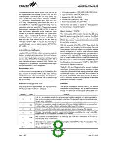
The functional unit chip reset status are shown below.
Program Counter
Interrupt
000H
Disable
Cleared
Prescaler, Divider
Clear. After master reset,
WDT begins counting
WDT
Timer/Event Counter Off
Input/Output Ports
Stack Pointer
Input mode
Points to the top of the stack
Rev. 1.40
11
July 12, 2005

 HOLTEK [ HOLTEK SEMICONDUCTOR INC ]