HT46R51/HT46R52
Oscillator Configuration
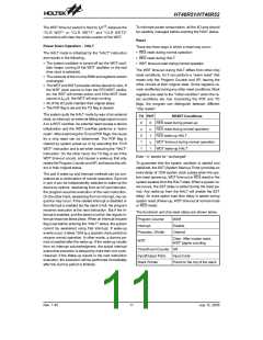
Watchdog Timer - WDT
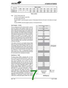
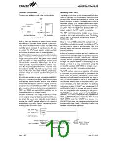
There are two oscillator circuits in the microcontroller.
The clock source of the WDT is implemented by a dedi-
cated RC oscillator (WDT oscillator) or instruction clock
(system clock divided by 4) decided by options. This
timer is designed to prevent a software mal-function or
sequence jumping to an unknown location with unpre-
dictable results. The watchdog timer can be disabled by
an option. If the watchdog timer is disabled, all the exe-
cutions related to the WDT result in no operation.
V
D
D
4
7
0
p
F
O
S
C
1
O
S
C
1
O
S
C
2
O
S
C
2
f
S
Y
S
/
4
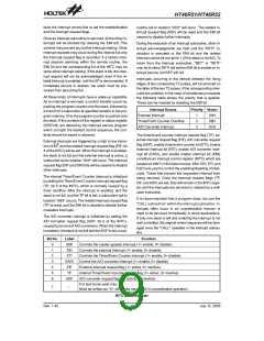
The WDT clock (fS) is further divided by an internal
counter to give longer watchdog time-outs. The division
ratio is fixed by an internal counter which gives a 215
fixed division ratio.
C
r
y
s
t
a
l
O
s
c
i
l
l
a
t
o
r
R
C
O
s
c
i
l
l
a
t
o
r
System Oscillator
Both of them are designed for system clocks, namely
the external RC oscillator and the external Crystal oscil-
lator, which are determined by options. No matter what
oscillator type is selected, the signal provides the sys-
tem clock. The HALT mode stops the system oscillator
and ignores an external signal to conserve power.
Once an internal WDT oscillator (RC oscillator with pe-
riod of 65ms normally) is selected, it is divided by 216 to
get the time-out period of approximately 4.3s. This
time-out period may vary with temperature, VDD and
process variations.
If the WDT oscillator is disabled, the WDT clock may still
come from the instruction clock and operate in the same
manner except that in the HALT state the WDT may stop
counting and lose its protecting purpose. In this situation
the logic can only be restarted by external logic. If the
device operates in a noisy environment, using the
on-chip RC oscillator (WDT OSC) is strongly recom-
mended, since the HALT will stop the system clock.
If an RC oscillator is used, an external resistor between
OSC1 and VSS is required and the resistance must
range from 30kW to 750kW. The system clock, divided
by 4, is available on OSC2 with pull-high resistor, which
can be used to synchronize external logic. The RC os-
cillator provides the most cost effective solution. How-
ever, the frequency of oscillation may vary with VDD,
temperatures and the chip itself due to process varia-
tions. It is therefore not suitable for timing sensitive op-
erations where an accurate oscillator frequency is
desired.
The WDT overflow under normal operation will initialize
a ²chip reset² and set the status bit TO. Whereas in the
HALT mode, the overflow will initialize a ²warm reset²
wherein only the Program Counter and SP are reset to
zero. To clear the contents of the WDT, three methods
are adopted; external reset (a low level to RES), soft-
ware instructions, or a HALT instruction. The software
instructions include ²CLR WDT² and the other set CLR
WDT1 and CLR WDT2. Of these two types of instruc-
tion, only one can be active depending on the option -
²CLR WDT times selection option². If the ²CLR WDT² is
selected (i.e. CLRWDT times equal one), any execution
of the CLR WDT instruction will clear the WDT. In case
²CLR WDT1² and ²CLR WDT2² are chosen (i.e.
CLRWDT times equal two), these two instructions must
be executed to clear the WDT; otherwise, the WDT may
reset the chip because of time-out.
If the Crystal oscillator is used, a crystal across OSC1
and OSC2 is needed to provide the feedback and phase
shift required for the oscillator, and no other external
components are required. Instead of a crystal, a resona-
tor can also be connected between OSC1 and OSC2 to
get a frequency reference, but two external capacitors in
OSC1 and OSC2 are required (If the oscillator can be
disabled by options to conserve power).
The WDT oscillator is a free running on-chip RC oscillator,
and no external components are required. Even if the sys-
tem enters the power down mode, the system clock is
stopped, but the WDT oscillator still works with a period of
approximately 65ms at 5V. The WDT oscillator can be dis-
abled by option to conserve power.
C
C
L
L
R
R
W
W
D
D
T
T
1
2
F
F
l
l
a
a
g
g
C
o
n
t
r
o
l
L
o
g
i
c
1
o
r
2
I
n
s
t
r
u
c
t
i
o
n
s
C
L
R
S
Y
S
W
D
T
S
o
o
u
r
c
e
8
f
S
S
f / 2
C
o
n
f
i
g
u
r
a
t
i
o
n
8
-
b
i
t
C
o
u
n
t
e
r
7
-
b
i
t
C
o
u
n
t
e
r
¸
2
W
D
T
T
i
m
e
-
o
u
t
O
p
t
i
n
W
D
T
O
s
c
i
l
l
a
t
o
r
1
5
1
6
(
2
/
f
S
~
2
S
/ f )
Watchdog Timer
Rev. 1.40
10
July 12, 2005

 HOLTEK [ HOLTEK SEMICONDUCTOR INC ]