HT46R51/HT46R52
tains the interrupt control bits to set the enable/disable
and the interrupt request flags.
routine call to location ²0CH² will occur. The related in-
terrupt request flag (ADF) will be reset and the EMI bit
cleared to disable further interrupts.
Once an interrupt subroutine is serviced, all the other in-
terrupts will be blocked (by clearing the EMI bit). This
scheme may prevent any further interrupt nesting. Other
interrupt requests may occur during this interval but only
the interrupt request flag is recorded. If a certain inter-
rupt requires servicing within the service routine, the
EMI bit and the corresponding bit of the INTC may be
set to allow interrupt nesting. If the stack is full, the inter-
rupt request will not be acknowledged, even if the re-
lated interrupt is enabled, until the SP is decremented. If
immediate service is desired, the stack must be pre-
vented from becoming full.
During the execution of an interrupt subroutine, other in-
terrupt acknowledgments are held until the ²RETI² in-
struction is executed or the EMI bit and the related
interrupt control bit are set to 1 (if the stack is not full). To
return from the interrupt subroutine, ²RET² or ²RETI²
may be invoked. RETI will set the EMI bit to enable an in-
terrupt service, but RET will not.
Interrupts, occurring in the interval between the rising
edges of two consecutive T2 pulses, will be serviced on
the latter of the two T2 pulses, if the corresponding inter-
rupts are enabled. In the case of simultaneous requests
the following table shows the priority that is applied.
These can be masked by resetting the EMI bit.
All these kinds of interrupts have a wake-up capability.
As an interrupt is serviced, a control transfer occurs by
pushing the program counter onto the stack, followed by
a branch to a subroutine at specified location in the pro-
gram memory. Only the program counter is pushed onto
the stack. If the contents of the register or status register
(STATUS) are altered by the interrupt service program
which corrupts the desired control sequence, the con-
tents should be saved in advance.
Interrupt Source
External Interrupt
Priority Vector
1
2
3
04H
08H
0CH
Timer/Event Counter Overflow
A/D Converter Interrupt
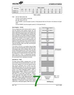
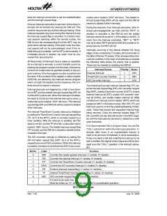
The timer/event counter interrupt request flag (TF), ex-
ternal interrupt request flag (EIF), A/D converter request
flag (ADF), enable timer/event counter bit (ETI), enable
external interrupt bit (EEI), enable A/D converter inter-
rupt bit (EADI), and enable master interrupt bit (EMI)
constitute an interrupt control register (INTC) which are
located at ²0BH² in the data memory. EMI, EEI, ETI, and
EADI are used to control the enabling/disabling of inter-
rupts. These bits prevent the requested interrupt from
being serviced. Once the interrupt request flags (TF,
EIF, and ADF) are set, they will remain in the INTC regis-
ter until the interrupts are serviced or cleared by a soft-
ware instruction.
External interrupts are triggered by a high to low transi-
tion of INT and the related interrupt request flag (EIF; bit
4 of the INTC) will be set. When the interrupt is enabled,
the stack is not full and the external interrupt is active, a
subroutine call to location ²04H² will occur. The interrupt
request flag (EIF) and EMI bits will be cleared to disable
other interrupts.
The internal Timer/Event Counter interrupt is initialized
by setting the Timer/Event Counter interrupt request flag
(TF; bit 5 of the INTC), which is normally caused by a
timer overflow. After the interrupt is enabled, and the
stack is not full, and the TF bit is set, a subroutine call to
location ²08H² occurs. The related interrupt request flag
(TF) is reset, and the EMI bit is cleared to disable further
maskable interrupts.
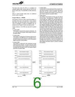
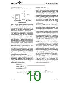
It is recommended that a program does not use the
²CALL subroutine² within the interrupt subroutine. In-
terrupts often occur in an unpredictable manner or
need to be serviced immediately in some applications.
If only one stack is left and enabling the interrupt is not
well controlled, the original control sequence will be dam-
aged once the ²CALL² operates in the interrupt subrou-
tine.
The A/D converter interrupt is initialized by setting the
A/D converter request flag (ADF; bit 6 of the INTC),
caused by an end of A/D conversion. When the interrupt
is enabled, the stack is not full and the ADF is set, a sub-
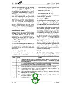
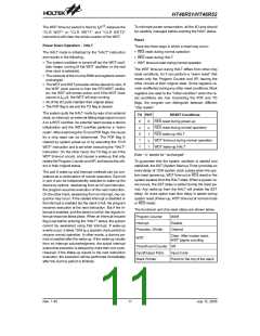
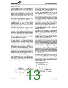
Bit No.
Label
EMI
EEI
Function
0
1
2
3
4
5
6
Controls the master (global) interrupt (1= enable; 0= disable)
Controls the external interrupt (1= enable; 0= disable)
Controls the Timer/Event Counter interrupt (1= enable; 0= disable)
Control the A/D converter interrupt (1= enable; 0= disable)
External interrupt request flag (1= active; 0= inactive)
Internal Timer/Event Counter request flag (1= active; 0= inactive)
A/D converter request flag (1= active; 0= inactive)
ETI
EADI
EIF
TF
ADF
For test mode used only.
7
¾
Must be written as ²0²; otherwise may result in unpredictable operation.
INTC (0BH) Register
Rev. 1.40
9
July 12, 2005

 HOLTEK [ HOLTEK SEMICONDUCTOR INC ]