HT46R63/HT46C63
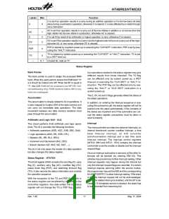
Labels
Bits
Function
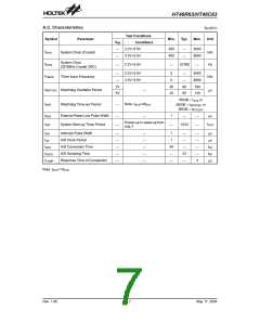
C is set if an operation results in a carry during an addition operation or if a borrow does not take
place during a subtraction operation; otherwise C is cleared. C is also affected by a rotate through
carry instruction.
C
0
AC is set if an operation results in a carry out of the low nibbles in addition or no borrow from the
high nibble into the low nibble in subtraction; otherwise AC is cleared.
AC
Z
1
2
3
Z is set if the result of an arithmetic or logical operation is zero; otherwise Z is cleared.
OV is set if the operation results in a carry into the highest-order bit but not a carry out of the high-
est-order bit, or vice versa; otherwise OV is cleared.
OV
PDF is cleared by a system power-up or executing the ²CLR WDT² instruction. PDF is set by exe-
cuting the ²HALT² instruction.
PDF
TO
4
TO is cleared by system power-up or executing the ²CLR WDT² or ²HALT² instruction. TO is set
by a WDT time-out.
5
6, 7
¾
Unused bit, read as ²0²
Status Register
Bank Pointer
tion operations related to the status register may give
different results from those intended. The TO flag
The bank pointer is used to assign the accessed RAM
bank. When the users want to access the RAM bank ²0²
a 0 should be loaded onto BP. When the BP is equal to
²1², the LCD RAM will be accessed (use MP1/R1 indi-
rect addressing only). RAM locations before 40H in any
bank are overlapped.
can be affected only by system power-up, a WDT
time-out or executing the ²CLR WDT² or ²HALT² in-
struction. The PDF flag can be affected only by exe-
cuting the ²HALT² or ²CLR WDT² instruction or a
system power-up.
The Z, OV, AC and C flags generally reflect the status of
the latest operations.
Accumulator
The accumulator is closely related to ALU operations. It
is also mapped to location 05H of the data memory and
can carry out immediate data operations. The data
movement between two data memory locations must
pass through the accumulator.
In addition, on entering the interrupt sequence or exe-
cuting the subroutine call, the status register will not be
pushed onto the stack automatically. If the contents of
the status are important and if the subroutine can cor-
rupt the status register, precautions must be taken to
save it properly.
Arithmetic and Logic Unit - ALU
Interrupt
This circuit performs 8-bit arithmetic and logic opera-
tions. The ALU provides the following functions:
The microcontroller provides two external interrupts, an
internal timer/event counter overflow interrupt, a time
base time-out interrupt, an A/D converter
end-of-conversion interrupt and a real time clock
time-out interrupt. The interrupt control registers
(INTC0: 0BH and INTC1: 1EH) contains the interrupt
control bits to set the enable or disable and the interrupt
request flags.
·
·
·
·
·
Arithmetic operations (ADD, ADC, SUB, SBC, DAA)
Logic operations (AND, OR, XOR, CPL)
Rotation (RL, RR, RLC, RRC)
Increment and Decrement (INC, DEC)
Branch decision (SZ, SNZ, SIZ, SDZ ....)
The ALU not only saves the results of a data operation
but also changes the status register.
Once an interrupt subroutine is serviced, all the other in-
terrupts will be blocked (by clearing EMI bit). This
scheme may prevent any further interrupt nesting. Other
interrupt requests may happen during this interval but
only the interrupt request flags are recorded. If a certain
interrupt requires servicing within the service routine,
the programmer may set the EMI and the corresponding
bit of INTC0/INTC1 to allow interrupt nesting. If the stack
is full, the interrupt request will not be acknowledged,
even if the related interrupt is enabled, until the SP is de-
creased. If immediate service is desired, the stack has
to be prevented from becoming full.
Status Register - STATUS
This 8-bit register (0AH) contains the zero flag (Z), carry
flag (C), auxiliary carry flag (AC), overflow flag (OV),
power down flag (PDF), and watchdog time-out flag
(TO). It also records the status information and controls
the operation sequence.
With the exception of the TO and PDF flags, bits in
the status register can be altered by instructions like
most other registers. Any data written into the status
register will not change the TO or PDF flag. In addi-
Rev. 1.90
11
May 17, 2004

 HOLTEK [ HOLTEK SEMICONDUCTOR INC ]