HT46R63/HT46C63
are determined by options. The HALT mode stops the
system oscillator and resists the external signal to con-
serve power. Another one is a 32768Hz crystal oscilla-
tor, which only provides use for real time clock. The
other one is a built-in 12KHz RC oscillator, which is used
for WDTOSC.
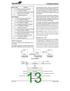
Bit No. Label
Function
External interrupt 1 request flag
(1= active; 0= inactive)
5
EIF1
Timer/Event Counter overflow request
flag (1= active; 0= inactive)
6
7
TF
¾
Unused bit, read as ²0²
If the system clock uses the external RC oscillator, an
external resistor between OSC1 and VDD is required
and the resistance should range from 24kW to 1MW. The
system clock, divided by 4, is available on OSC2, which
can be used to synchronize external logic.
INTC1 Register
Controls the time base interrupt
(1= enabled; 0= disabled)
0
1
ETBI
EADI
Controls the A/D converter interrupt
(1= enabled; 0= disabled)
If the system clock uses the crystal oscillator, a crystal
across OSC1 and OSC2 is needed to provide the feed-
back and phase shift required for the oscillator, and no
other external components are demanded. Instead of a
crystal, the resonator can also be connected between
OSC1 and OSC2 to get a frequency reference, but two
external capacitors in OSC1 and OSC2 are required.
Controls the real time clock interrupt
(1= enabled; 0= disabled)
2
3
4
ERTI
¾
Unused bit, read as ²0²
Time base time-out interrupt 0 request
flag (1= active; 0= inactive)
TBF
If the RTCOSC is used, a crystal across OSC3 and
OSC4 is needed to provide the feedback and phase
shift required for the oscillator, and no other external
components are demanded.
End of A/D conversion interrupt request
flag (1= active; 0= inactive)
5
ADF
RTC time-out interrupt request flag
(1= active; 0= inactive)
6
7
RTF
Watchdog Timer - WDT
¾
Unused bit, read as ²0²
The clock source of WDT (and LCD, RTC, Time Base )
is implemented by a dedicated crystal oscillator
(32.768kHz: RTCOSC) or instruction clock (system fre-
quency divided by 4: fSYS/4) or a dedicated RC oscillator
(12KHz:WDTOSC) decided by options. This timer is de-
signed to prevent a software malfunction or sequence
from jumping to an unknown location with unpredictable
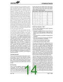
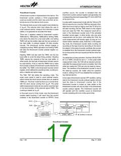
Oscillator Configuration
There are four oscillator circuits implemented in the mi-
cro-controller.
Two of them are designed for system clocks, namely the
external RC oscillator and the crystal oscillator, which
V
D
D
O
S
C
1
O
S
C
3
3
2
7
6
8
H
z
O
O
S
S
C
C
1
2
X
'
t
a
l
S
Y
S
O
S
C
2
O
S
C
4
N
M
O
S
O
p
e
n
D
r
a
i
n
C
r
y
s
t
a
l
O
s
c
i
l
l
a
t
o
r
E
x
t
e
r
n
a
l
R
C
O
s
c
i
l
l
a
t
o
r
C
r
y
s
t
a
l
O
s
c
i
l
l
a
t
o
r
f
o
r
s
y
s
t
e
m
c
l
o
c
k
f
o
r
s
y
s
t
e
m
c
l
o
c
k
f
o
r
R
T
C
O
S
C
System Oscillator
C
L
R
W
D
T
W
D
T
O
S
C
M
f
S
Y
S
/
4
f
S
U
1
6
-
B
i
t
C
o
u
n
t
e
r
D
W
D
T
t
i
m
e
-
o
u
t
R
T
C
O
S
C
X
R
E
S
1
5
-
B
i
t
C
o
u
n
t
e
r
1
2
1
5
O
O
p
p
t
t
i
i
o
o
n
n
s
s
4
t
o
1
M
U
X
T
i
m
e
b
a
s
e
:
f
S
/
2
S
~ f / 2
2
8
7
t
o
1
M
U
X
L
C
D
f
r
e
f
q
u
e
n
c
y
:
f
S
/
2
~
f
S
/
2
8
1
5
R
T
C
C
.
2
~
R
T
C
C
.
0
8
t
o
1
M
U
X
R
T
C
:
S
/
2
~
f
S
/
2
Watchdog Timer
Rev. 1.90
13
May 17, 2004

 HOLTEK [ HOLTEK SEMICONDUCTOR INC ]