HT46R63/HT46C63
Functional Description
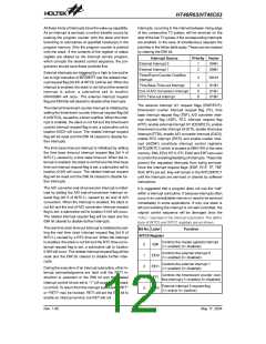
Execution Flow
When executing a jump instruction, conditional skip ex-
ecution, loading PCL (program counter lower-order byte
register), subroutine call, initial reset, interrupts or return
from subroutine or interrupts, the program counter ma-
nipulates the program transfer by loading the address
corresponding to each instruction.
The system clock for the microcontroller is derived from
an external RC or crystal oscillator. The system clock is
internally divided into four non-overlapping clocks. One
instruction cycle consists of 4 system clock cycles.
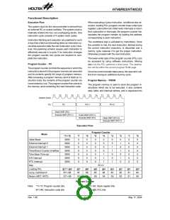
Instruction fetching and execution are pipelined in such
a way that a fetch and decoding takes an instruction cy-
cle while execution take the next instruction cycle. How-
ever, the pipelining scheme causes each instruction to
effectively execute in a cycle. If an instruction changes
the program counter, two cycles are required to com-
plete the instruction.
The conditional skip is activated by instructions. Once
the condition is met, the next instruction, fetched during
the current instruction execution, is discarded and a
dummy cycle replaces it to get the proper instruction.
Otherwise proceed with the next instruction.
The lower-order byte of the program counter (PCL) can
be accessed by using software instructions. Moving
data into the PCL performs a short jump. The destina-
tion will be within the current program ROM page.
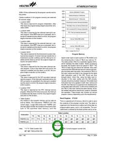
Program Counter - PC
The program counter controls the sequence in which the
instructions stored in the program memory are executed
and its contents specify full range of program memory.
After accessing a program memory word to fetch an in-
struction code, the contents of the program counter are
incremented by one. The program counter then points to
the memory word containing the next instruction code.
Once the control transfer takes place, the execution suf-
fers from having an additional dummy cycle.
Program Memory - PROM
The program memory is used to store the program in-
structions which are to be executed. It also contains
data, table, and interrupt entries, and is organized into
T
1
T
2
T
3
T
4
T
1
T
2
T
3
T
4
T
1
T
2
T
3
T
4
S
y
s
t
e
m
C
l
o
c
k
P
C
P
C
+
1
P
C
+
2
P
C
F
e
t
c
h
I
N
S
T
(
P
C
)
E
x
e
c
u
t
e
I
N
S
T
(
P
C
-
1
)
F
e
t
c
h
I
N
S
T
(
P
C
+
1
)
E
x
e
c
u
t
e
I
N
S
T
(
P
C
)
F
e
t
c
h
I
N
S
T
(
P
C
+
2
)
E
x
e
c
u
t
e
I
N
S
T
(
P
C
+
1
)
Execution Flow
Program Counter
Mode
*11~*8
0000
0000
0000
0000
0000
0000
0000
*7
0
0
0
0
0
0
0
*6
0
0
0
0
0
0
0
*5
0
0
0
0
0
0
0
*4
0
0
0
0
1
1
1
*3
0
0
1
1
0
0
1
*2
0
1
0
1
0
1
0
*1
0
0
0
0
0
0
0
*0
0
0
0
0
0
0
0
Initial Reset
External Interrupt 0
External Interrupt 1
Timer/Event Counter Overflow
Time Base Time-out
A/D Interrupt
RTC Interrupt
Skip
PC+2
Loading PCL
@11~@8
#11~#8
@7
#7
@6
#6
@5
#5
@4
#4
@3
#3
@2
#2
@1
#1
@0
#0
Jump, Call Branch
Return (RET, RETI)
S11~S8
S7
S6
S5
S4
S3
S2
S1
S0
Program Counter
Note: *11~*0: Program counter bits
#11~#0: Instruction code bits
S11~S0: Stack register bits
@7~@0: PCL bits
Rev. 1.90
8
May 17, 2004

 HOLTEK [ HOLTEK SEMICONDUCTOR INC ]