HT46R63/HT46C63
Once a wake-up event occurs, it takes 1024 tSYS (sys-
tem clock period) to resume normal operation. In other
words, a dummy period will be inserted after wake-up. If
the wake-up results from an interrupt acknowledgment,
the actual interrupt subroutine execution will be delayed
by one or more cycles. If the wake-up results in the next
instruction execution, this will be executed immediately
after the dummy period is finished.
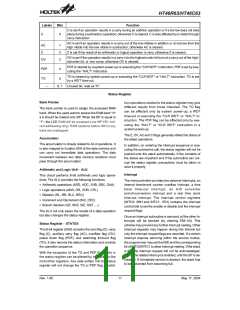
The chip reset statuses of the functional units are as
shown.
PC
000H
Interrupt
Disable
Clear. After master reset, WDT
begins counting
WDT
Timer/Event Counter Off
To minimize power consumption, all the I/O pins should
be carefully managed before entering the HALT status.
Input/Output Ports
SP
Input mode
Points to the top of the stack
The 32.768kHz crystal oscillator still run or stop in the
halt mode. (decided by option)
V
D
D
Reset
m
0 . 0 1 F *
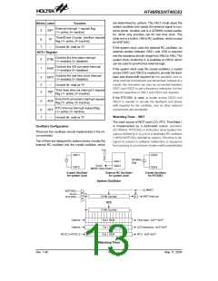
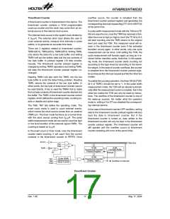
There are three ways in which a reset can occur:
1
0
0
k
·
·
·
RES reset during normal operation
RES reset during HALT
R
E
S
1
0
k
WDT time-out reset during normal operation
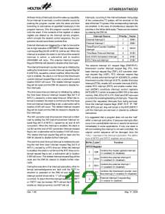
The WDT time-out during HALT is different from other
chip reset conditions, since it can perform a ²warm re -
set² that resets only the PC and SP, leaving the other cir-
cuits in their original state. Some registers remain un-
changed during other reset conditions. Most registers
are reset to the ²initial condition² when the reset condi-
tions are met. By examining the PDF and TO flags, the
program can distinguish between different ²chip resets².
m
0 . 1 F *
Reset Circuit
Note:
²*² Make the length of the wiring, which is con-
nected to the RES pin as short as possible, to
avoid noise interference.
H
A
L
T
TO PDF
Reset Conditions
RES reset during power-up
RES reset during normal operation
RES wake-up HALT
W
a
r
m
R
e
s
e
t
W
D
T
0
u
0
1
1
0
u
1
u
1
R
E
S
C
o
l
d
R
e
s
e
t
WDT time-out during normal operation
WDT wake-up HALT
S
S
T
1
0
-
b
i
t
R
i
p
p
l
e
O
S
C
1
C
o
u
n
t
e
r
Note: ²u² means unchanged
S
y
s
t
e
m
R
e
s
e
t
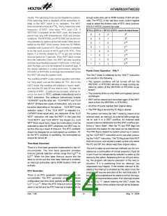
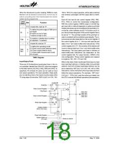
To guarantee that the system oscillator is started and
stabilized, the SST (system start-up timer) provides an
extra-delay to delay 1024 system clock pulses when
system power-up or the system awakes from the HALT
state.
Reset Configuration
V
D
D
R
E
S
t
S S T
When the system power-up occurs, the SST delay is
added during the reset period. But when the reset co-
mes from the RES pin, the SST delay is disabled. Any
wake-up from HALT will enable the SST delay.
S
S
T
T
i
m
e
-
o
u
t
C
h
i
p
R
e
s
e
t
Reset Timing Chart
An extra option load time delay is added during system
reset (power-up, WDT time-out at normal mode or RES
reset).
Rev. 1.90
15
May 17, 2004

 HOLTEK [ HOLTEK SEMICONDUCTOR INC ]