HT46R63/HT46C63
0
0
0
0
0
4
H
H
D
e
v
i
c
e
I
n
i
t
i
a
l
i
z
a
t
i
o
n
P
r
o
g
r
a
m
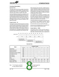
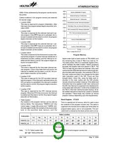
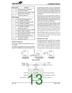
4096´15 bits, addressed by the program counter and ta-
ble pointer.
E
x
t
e
r
n
a
l
I
n
t
e
r
r
u
p
t
0
S
u
b
r
o
u
t
i
n
e
0
0
8
H
Certain locations in the program memory are reserved
for special usage:
E
x
t
e
r
n
a
l
I
n
t
e
r
r
u
p
t
1
S
u
b
r
o
u
t
i
n
e
0
0
C
H
·
·
Location 000H
T
i
m
e
r
/
E
v
e
n
t
C
o
u
n
t
e
r
I
n
t
e
r
r
u
p
t
S
u
b
r
o
u
t
i
n
e
0
0
0
1
1
1
0
4
8
H
H
H
This area is reserved for program initialization. After
chip reset, the program always begins execution at lo-
cation 000H.
T
i
m
e
B
a
s
e
T
i
m
e
-
o
u
t
I
n
t
e
r
r
u
p
t
S
u
b
r
o
u
t
i
n
e
P
r
o
g
r
a
m
M
e
m
o
r
y
A
/
D
C
o
n
v
e
r
t
e
r
E
O
C
I
n
t
e
r
r
u
p
t
S
u
b
r
o
u
t
i
n
e
Location 004H
R
T
C
T
i
m
e
-
o
u
t
I
n
t
e
r
r
u
p
t
s
u
b
r
o
u
t
i
n
e
This area is reserved for the external interrupt 0 ser-
vice program. If the INT0 input pin is activated, the in-
terrupt is enabled and the stack is not full, the program
begins execution at this location.
n
0
0
H
L
o
o
k
-
u
p
T
a
b
l
e
(
2
5
6
w
o
r
d
s
)
n
F
F
H
·
·
Location 008H
This area is reserved for the external interrupt 1 ser-
vice program. If the INT1 input pin is activated, the in-
terrupt is enabled and the stack is not full, the program
begins execution at this location.
F
0
0
H
L
o
o
k
-
u
p
T
a
b
l
e
(
2
5
6
w
o
r
d
s
)
F
F
F
H
1
5
b
i
t
s
N
o
t
e
:
n
r
a
n
g
e
s
f
r
o
m
0
t
o
F
Location 00CH
This area is reserved for the timer/event counter inter-
rupt service program. If a timer interrupt results from a
timer/event counter overflow, and the interrupt is en-
abled and the stack is not full, the program begins ex-
ecution at location 00CH.
Program Memory
higher-order byte to lower portion of TBLH(08H) and
the remaining bits (1 bits) of TBLH are read as ²0².
The table pointer (TBLP) is read/write register (07H),
which indicates the table location. Before accessing
the table, the location has to be placed in TBLP. The
TBLH is read only and cannot be restored. If the main
routine and the ISR(interrupt service routine) both em-
ploy the table read instruction, the contents of TBLH in
the main routine are likely to be changed by the table
read instruction used in the ISR. Errors are thus
brought about. Given this, using the table read in-
struction in the main routine and the ISR simulta-
neously should be avoided. However, if the table read
instruction has to be applied in both main routine and
the ISR, the interrupt is supposed to be disabled prior
to the table read instruction. It will not be enabled until
the TBLH in the main routine has been backup. All ta-
ble related instructions require two cycles to complete
the operation. These areas may function as normal
program memory depending upon the requirements.
·
·
Location 010H
This area is reserved for the time base interrupt ser-
vice program. If the a time base time-out occurs, the
interrupt is enabled and the stack is not full, the pro-
gram begins execution at this location.
Location 014H
This area is reserved for the A/D converter interrupt
service program. If the interrupt is activated (when the
A/D conversion is completed), the interrupt is enabled
and the stack is not full, the program begins execution
at this location.
·
·
Location 018H
This area is reserved for the RTC interrupt service
program. When the RTC time-out occurs, the interrupt
is enabled and the stack is not full, the program begins
execution at this location.
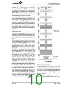
Stack Register - STACK
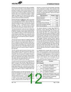
Table location
Any location in the program memory can be used as
look-up tables. The instructions ²TABRDC [m]² (the
current page, 1 page=256 words) and ²TABRDL [m]²
(the last page) transfer the contents of the lower-order
byte to the specified data memory, and the
This is a special part of memory, which is used to save
the contents of the program counter only. The stack is
organized into 8 levels and is neither part of the data not
programmable space, and is not accessible. The acti-
vated level is indexed by the stack pointer and is not ac-
Table Location
Instruction
*11
P11
1
*10
P10
1
*9
P9
1
*8
P8
1
*7
*6
*5
*4
*3
*2
*1
*0
TABRDC [m]
TABRDL [m]
@7
@7
@6
@6
@5
@5
@4
@4
@3
@3
@2
@2
@1
@1
@0
@0
Table Location
P11~P8: Current program counter bits
Note: *11~*0: Table location bits
@7~@0: Table pointer bits
Rev. 1.90
9
May 17, 2004

 HOLTEK [ HOLTEK SEMICONDUCTOR INC ]