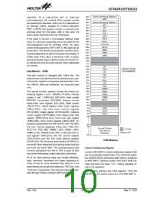
HT46R63/HT46C63
results. The watchdog timer can be disabled by options.
If the watchdog timer is disabled, all the executions re-
lated to the WDT result in no operation. The WDT
time-out period is fixed as 216/fS. The fS means the clock
frequency of WDT, time base, RTC and LCD. If
WDTOSC is selected as the WDT clock, the time-out
period may vary with temperatures, VDD and process
variations. The WDTOSC and RTCOSC can be still run-
ning (decided by option) at the halt mode if they are se-
lected as the WDT clock source. Once the 32.768kHz
oscillator (with a period of 31.25ms normally) is selected
to be the clock source of WDT (and LCD, RTC, Time
Base), it is directly divided by 216 to get the nominal
time-out period of 2 seconds. If the WDT clock comes
from the instruction clock, the WDT will stop counting
and lose its protecting purpose in halt mode. In this situ-
ation the logic can only be restarted by external logic. If
the device operates in a noisy environment, using the
RTCOSC or WDTOSC is strongly recommended, since
the HALT will stop the system clock.
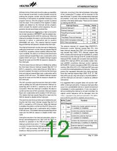
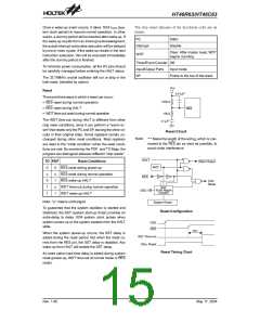
terrupt subroutine call to ROM location 018H will acti-
vate. The RTCC is the real time clock control register
used to select the division ratio of RTC clock sources.
RTCC.7~RTCC.3 cannot be used.
RTCC.2 RTCC.1 RTCC.0 RTC clock divided factor
0
0
0
0
1
1
1
1
0
0
1
1
0
0
1
1
0
1
0
1
0
1
0
1
28
29
210
211
212
213
214
215
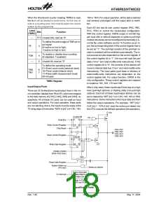
Power Down Operation - HALT
The HALT mode is initialized by the ²HALT² instruction
and results in the following...
The overflow of WDT under normal operation will initial-
ize ²chip reset² and set the status bit ²TO². But in the
HALT mode, the overflow will initialize a ²warm reset²,
and only the PC and SP are reset to zero. To clear the
contents of WDT , 3 methods are adopted; external re-
set (a low level to RES), software instruction(s) and a
HALT instruction. The software instruction(s) include
²CLR WDT² and the other set - ²CLR WDT1² and ²CLR
WDT2² Of these two types of instruction, only one can
be active depending on the options - ²CLR WDT times
selection option². If the ²CLR WDT² is selected (i.e.
CLRWDT times equal one), any execution of the ²CLR
WDT² instruction will clear the WDT. In the case that
²CLR WDT1² and ²CLR WDT2² are chosen (i.e. CLR
WDT times equal two), these two instructions must be
executed to clear the WDT; otherwise, the WDT may re-
set the chip as a result of time-out. The RTC oscillator
should be designed as an auto-speed-up oscillator. Af-
ter the RTC oscillator is oscillating, the auto-speed-up
should be turned off.
·
The system oscillator will be turned off but the
WDTOSC or RTCOSC will stop or keep running de-
cided by option (If the WDTOSC or RTCOSC is se-
lected)
·
·
The contents of the on-chip RAM and registers remain
unchanged.
WDT will be cleared and recounted again (if the WDT
clock is from the WDTOSC or RTCOSC).
·
·
All of the I/O ports maintain their original status.
The PDF flag is set and the TO flag is cleared.
The system can leave the HALT mode by means of an
external reset, an interrupt, an external falling edge sig-
nal on port A or a WDT overflow. An external reset
causes a device initialization and the WDT overflow per-
forms a ²warm reset². After the TO and PDF flags are
examined, the reason for chip reset can be determined.
The PDF flag is cleared by system power-up or execut-
ing the ²CLR WDT² instruction and is set when execut-
ing the ²HALT² instruction. The TO flag is set if the WDT
time-out occurs, and causes a wake-up that only resets
the PC and SP; the others keep their original status.
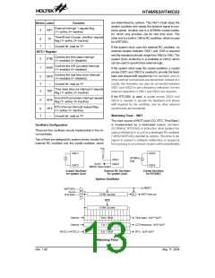
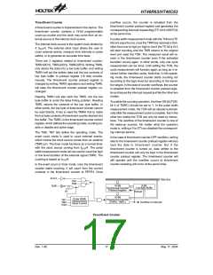
Time Base Generator
There is a time base generator implemented in the mi-
cro-controller. The time base generator provides
time-out periods selection whose range from fS/212 to
fS/215. When the time base time-out occurs and the
stack is not full and the time base interrupt is enabled,
an interrupt subroutine call to ROM location 010H will
activate.
The port A wake-up and interrupt methods can be con-
sidered as a continuation of normal execution. Each bit
in port A can be independently selected to wake up the
device by the option. Awakening from an I/O port stimu-
lus, the program will resume execution of the next in-
struction. If it is awakening from an interrupt, two
sequences may happen. If the related interrupt is dis-
abled or the interrupt is enabled but the stack is full, the
program will resume execution at the next instruction. If
the interrupt is enabled and the stack is not full, the regu-
lar interrupt response takes place. If an interrupt request
flag is set to ²1² before entering the HALT mode, the
wake-up function of the related interrupt will be disabled.
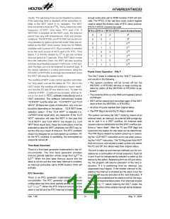
RTC Generator
There is an RTC generator implemented in the mi-
cro-controller. The RTC generator provides software
configurable real time clock periods whose range from
fS/28 to fS/215. When the RTC time-out occurs and the
stack is not full and the RTC interrupt is enabled, an in-
Rev. 1.90
14
May 17, 2004

 HOLTEK [ HOLTEK SEMICONDUCTOR INC ]