HT37B90/HT37B70/HT37B50/HT37B30
small differences in measured values requiring pro-
grammers to take this into account during programming.
The same applies if the timer is configured to be in the
event counting mode, which again is an external event
and not synchronized with the internal system or timer
clock. When the Timer/Event Counter is read, or if data
is written to the preload register, the clock is inhibited to
avoid errors, however as this may result in a counting er-
ror, this should be taken into account by the program-
mer. Care must be taken to ensure that the timers are
properly initialized before using them for the first time.
The associated timer enable bits in the interrupt control
register must be properly set otherwise the internal in-
terrupt associated with the timer will remain inactive.
The edge select, timer mode and clock source control
bits in timer control register must also be correctly set to
ensure the timer is properly configured for the required
application. It is also important to ensure that an initial
value is first loaded into the timer registers before the
timer is switched on; this is because after power-on the
initial values of the timer registers are unknown. After
the timer has been initialized the timer can be turned on
and off by controlling the enable bit in the timer control
register. Note that setting the timer enable bit high to
turn the timer on, should only be executed after the timer
mode bits have been properly setup. Setting the timer
enable bit high together with a mode bit modification,
may lead to improper timer operation if executed as a
single timer control register byte write instruction. When
the Timer/Event counter overflows, its corresponding in-
terrupt request flag in the interrupt control register will be
set. If the timer interrupt is enabled this will in turn gener-
ate an interrupt signal. However irrespective of whether
the interrupts are enabled or not, a Timer/Event counter
overflow will also generate a wake-up signal if the de-
vice is in a Power-down condition. This situation may
occur if the Timer/Event Counter is in the Event
Counting Mode and if the external signal continues to
change state. In such a case, the
Timer/Event Counter will continue to count these exter-
nal events and if an overflow occurs the device will be
woken up from its Power-down condition. To prevent
such a wake-up from occurring, the timer interrupt re-
quest flag should first be set high before issuing the
HALT instruction to enter the Power Down Mode.
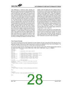
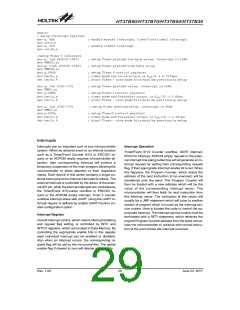
Timer Program Example
This program example shows how the Timer/Event Counter registers are setup, along with how the interrupts are en-
abled and managed. Note how the Timer/Event Counter is turned on, by setting bit 4 of the Timer Control Register. The
Timer/Event Counter can be turned off in a similar way by clearing the same bit.
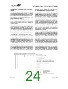
This example program sets the Timer/Event Counter to be in the timer mode, which uses the internal system clock as
the clock source. Show how to counter TMR0=1kHz, TMR1=2kHz, TMR2=4kHz, if fOSC is 11.059MHz.
org 00h
; Reset
jmp begin
org 04h
reti
; external interrupt vector
org 08h
jmp tmr0int
org 0ch
jmp tmr1int
org 10h
jmp tmr2int
; Timer/Event Counter 0 interrupt vector
; jump here when Timer0 overflows
; Timer/Event Counter 1 interrupt vector
; jump here when Timer1 overflows
; Timer Counter 2 interrupt vector
; jump here when Timer2 overflows
org 20h ; main program
;internal Timer0,1,2 Counter interrupt routine
tmr0int:
; Timer/Event Counter 0 main program placed here
:
reti
tmr1int:
; Timer/Event Counter 1 main program placed here
:
reti
tmr2int:
; Timer Counter 2 main program placed here
:
reti
:
Rev. 1.00
28
June 22, 2017

 HOLTEK [ HOLTEK SEMICONDUCTOR INC ]