HT37B90/HT37B70/HT37B50/HT37B30
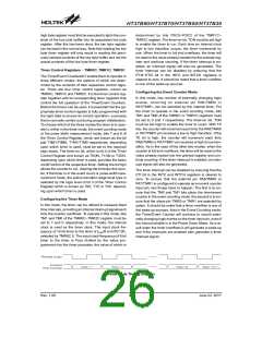
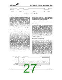
Event Counter Mode Timing Diagram
Configuring the Pulse Width Measurement Mode
Prescaler
In this mode, the width of external pulses applied to the
pin-shared external pin PA6/TMR0 or PA7/TMR1 can be
measured. In the Pulse Width Measurement Mode, the
timer clock source is supplied by the internal clock. For
the timer to operate in this mode, bits TM0 and TM1
must both be set high. If the TE bit is low, once a high to
low transition has been received on the PA6/TMR0 or
PA7/TMR1 pin, the timer will start counting until the
PA6/TMR0 or PA7/TMR1 pin returns to its original high
level. At this point the TON bit will be automatically reset
to zero and the timer will stop counting. If the TE bit is
high, the timer will begin counting once a low to high
transition has been received on the PA6/TMR0 or
PA7/TMR1 pin and stop counting when the PA6/TMR0
or PA7/TMR1 pin returns to its original low level. As be-
fore, the TON bit will be automatically reset to zero and
the timer will stop counting. It is important to note that in
the Pulse Width Measurement Mode, the TON bit is au-
tomatically reset to zero when the external control signal
on the external timer pin returns to its original level,
whereas in the other two modes the TON bit can only be
reset to zero under program control. The residual value
in the timer, which can now be read by the program,
therefore represents the length of the pulse received on
pin PA6/TMR0 or PA7/TMR1. As the TON bit has now
been reset any further transitions on the PA6/TMR0 or
PA7/TMR1 pin will be ignored. Not until the TON bit is
again set high by the program can the timer begin fur-
ther pulse width measurements. In this way single shot
pulse measurements can be easily made. It should be
noted that in this mode the counter is controlled by logi-
cal transitions on the PA6/TMR0 or PA7/TMR1 pin and
not by the logic level.
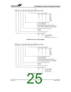
Bits PSC0~PSC2 of the TMRC1~ TMRC2 registers can
be used to define the pre-scaling stages of the internal
clock sources of the Timer/Event Counter.
Note: Because the two timers are used by MIDI the ex-
ternal timer pin functions are disabled.
I/O Interfacing
The Timer/Event Counter, when configured to run in the
event counter or pulse width measurement mode, re-
quire the use of the external PA6/TMR0 or PA7/TMR1
pin for correct operation. As this pin is a shared pin it
must be configured correctly to ensure it is setup for use
as a Timer/Event Counter input and not as a normal I/O
pin. This is implemented by ensuring that the mode se-
lect bits in the Timer/Event Counter control register, se-
lect either the event counter or pulse width
measurement mode. Additionally the PA share pin op-
tion must be selected to ensure that the pin is setup as
an TMR0 and TMR1 input.
Programming Considerations
When configured to run in the timer mode, the internal
system clock fOSC/8 is used as the timer clock source
and is therefore synchronized with the overall operation
of the microcontroller. In this mode when the appropriate
timer register is full, the microcontroller will generate an
internal interrupt signal directing the program flow to the
respective internal interrupt vector. For the pulse width
measurement mode, the internal system clock is also
used as the timer clock source but the timer will only run
when the correct logic condition appears on the external
timer input pin. As this is an external event and not syn-
chronized with the internal timer clock, the
microcontroller will only see this external event when the
next timer clock pulse arrives. As a result, there may be
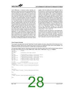
Pulse Width Measure Mode Timing Diagram
Rev. 1.00
27
June 22, 2017

 HOLTEK [ HOLTEK SEMICONDUCTOR INC ]