HT37B90/HT37B70/HT37B50/HT37B30
Once an interrupt subroutine is serviced, all the other in-
terrupts will be blocked, as the EMI bit will be cleared au-
tomatically.
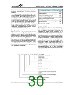
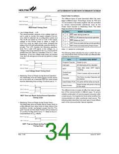
Interrupt Source
Priority Vector
Reset
1
2
3
4
00H
04H
08H
0CH
External Interrupt
This will prevent any further interrupt nesting from oc-
curring. However, if other interrupt requests occur dur-
ing this interval, although the interrupt will not be
immediately serviced, the request flag will still be re-
corded. If an interrupt requires immediate servicing
while the program is already in another interrupt service
routine, the EMI bit should be set after entering the rou-
tine, to allow interrupt nesting. If the stack is full, the in-
terrupt request will not be acknowledged, even if the
related interrupt is enabled, until the Stack Pointer is
decremented. If immediate service is desired, the stack
must be prevented from becoming full.
Timer/Event Counter 0 Overflow
Timer/Event Counter 1 Overflow
Timer Counter 2 overflow or UART
Interrupt
5
10H
ERCOCI Interrupt
6
7
14H
18H
ADPCM Empty Interrupt
External Interrupt
For an external interrupt to occur, the global interrupt en-
able bit, EMI, and external interrupt enable bit, EEI,
must first be set. An actual external interrupt will take
place when the external interrupt request flag, EIF, is
set, a situation that will occur when a high to low transi-
tion appears on the INT line. The external interrupt pin is
pin-shared with the I/O pin PA5 and can only be config-
ured as an external interrupt pin if the corresponding ex-
ternal interrupt enable bit in the INTC register has been
set. The pin must also be selected as by setting the cor-
responding PAC.5 bit in the port control register. When
the interrupt is enabled, the stack is not full and a high to
low transition appears on the external interrupt pin, a
subroutine call to the external interrupt vector at location
04H, will take place. When the interrupt is serviced, the
external interrupt request flag, EIF, will be automatically
reset and the EMI bit will be automatically cleared to dis-
able other interrupts.
Interrupt Priority
Interrupts, occurring in the interval between the rising
edges of two consecutive T2 pulses, will be serviced on
the latter of the two T2 pulses, if the corresponding inter-
rupts are enabled. In case of simultaneous requests, the
following table shows the priority that is applied. These
can be masked by resetting the EMI bit. In cases where
both external and internal interrupts are enabled and
where an external and internal interrupt occurs simulta-
neously, the external interrupt will always have priority
and will therefore be serviced first. Suitable masking of
the individual interrupts using the INTC register can pre-
vent simultaneous occurrences.
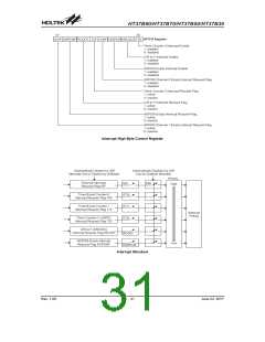
Interrupt Low Byte Control Register
Rev. 1.00
30
June 22, 2017

 HOLTEK [ HOLTEK SEMICONDUCTOR INC ]