HT37B90/HT37B70/HT37B50/HT37B30
begin:
; setup interrupt register
mov a, 0bh
mov intc,a
mov a, 01h
mov intch,a
; enable master interrupt, timer0 and timer1 interrupt
; enable timer2 interrupt
;setup Timer 0 registers
mov a, low (65536-1382)
mov TMR0L,a;
mov a, high (65536-1382)
mov TMR0H,a;
mov a,080h
; setup Timer preload low byte value, interrupt in 1kHz
; setup Timer preload high byte value
; setup Timer 0 control register
mov tmr0c,a
set tmr0c.4
; timer mode and clock source is fOSC/8 ® 0.7234ms
; start Timer - note mode bits must be previously setup
mov a, low (256-173)
mov TMR1,a;
mov a,080h
; setup Timer preload value, interrupt in 2kHz
; setup Timer 1control register
mov tmr1c,a
set tmr1c.4
; timer mode and Prescaler output is fOSC/32 ® 2.89ms
; start Timer - note mode bits must be previously setup
mov a, low (256-173)
mov TMR2,a;
mov a,080h
; setup Timer preload value, interrupt in 4kHz
; setup Timer2 control register
mov tmr2c,a
set tmr2c.4
; timer mode and Prescaler output is fOSC/16 ® 1.447ms
; start Timer - note mode bits must be previously setup
Interrupts
Interrupts are an important part of any microcontroller
system. When an external event or an internal function
such as a Timer/Event Counter 0/1/2 or ERCOCI re-
quire or an ADPCM empty requires microcontroller at-
tention, their corresponding interrupt will enforce a
temporary suspension of the main program allowing the
microcontroller to direct attention to their respective
needs. Each device in this series contains a single ex-
ternal interrupt and two internal interrupts functions. The
external interrupt is controlled by the action of the exter-
nal INT pin, while the internal interrupts are controlled by
the Timer/Event 0/1Counter overflow or ERCOCI re-
quire or the ADPCM empty interrupt. Timer 2 counter
overflow interrupt share with UART. Using the UART in-
terrupt require is defined by enable UART function en-
able configuration option.
Interrupt Operation
Timer/Event 0/1/2 Counter overflow, UART interrupt,
ERCOCI interrupt, ADPCM empty request or the exter-
nal interrupt line being pulled low will all generate an in-
terrupt request by setting their corresponding request
flag, if their appropriate interrupt enable bit is set. When
this happens, the Program Counter, which stores the
address of the next instruction to be executed, will be
transferred onto the stack. The Program Counter will
then be loaded with a new address which will be the
value of the corresponding interrupt vector. The
microcontroller will then fetch its next instruction from
this interrupt vector. The instruction at this vector will
usually be a JMP statement which will jump to another
section of program which is known as the interrupt ser-
vice routine. Here is located the code to control the ap-
propriate interrupt. The interrupt service routine must be
terminated with a RETI statement, which retrieves the
original Program Counter address from the stack and al-
lows the microcontroller to continue with normal execu-
tion at the point where the interrupt occurred.
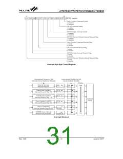
Interrupt Register
Overall interrupt control, which means interrupt enabling
and request flag setting, is controlled by INTC and
INTCH registers, which are located in Data Memory. By
controlling the appropriate enable bits in this register
each individual interrupt can be enabled or disabled.
Also when an interrupt occurs, the corresponding re-
quest flag will be set by the microcontroller. The global
enable flag if cleared to zero will disable all interrupts.
Rev. 1.00
29
June 22, 2017

 HOLTEK [ HOLTEK SEMICONDUCTOR INC ]