HT37B90/HT37B70/HT37B50/HT37B30
Configuring the Timer/Event Counter Input Clock
Source
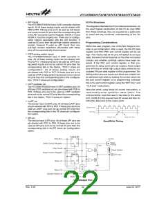
generated. The timer value will then be reset with the ini-
tial preload register value and continue counting.
Note that to achieve a maximum full range count of FFH
for the 8-bit timer or FFFFH for the 16-bit timers, the
preload registers must first be cleared to all zeros. It
should be noted that after power-on, the preload regis-
ters will be in an unknown condition. Note that if the
Timer/Event Counters are in an OFF condition and data
is written to their preload registers, this data will be im-
mediately written into the actual counter. However, if the
counter is enabled and counting, any new data written
into the preload data register during this period will re-
main in the preload register and will only be written into
the actual counter the next time an overflow occurs.
Note also that when the timer registers are read, the
timer clock will be blocked to avoid errors, however, as
this may result in certain timing errors, programmers
must take this into account.
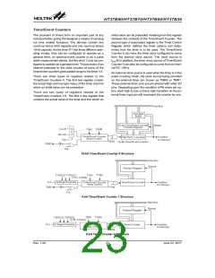
The internal timer¢s clock can originate from various
sources, depending upon timer is chosen. The system
clock input timer source is used when the timer is in the
timer mode or in the pulse width measurement mode.
For Timer/Event Counter 0, these system clock timer
source is selected by TMR0C.5.
For Timer/Event Counter 1, 2 this system clock timer
source is first divided by a prescaler, the division ratio of
which is conditioned by the Timer Control Register bits
T1PSC0~T1PSC2.
An external clock source is used when the timer is in the
event counting mode, the clock source being provided
on the external timer pin, known as TMR0 or TMR1.
These external timer pins are pin-shared with other I/O
pins. Depending upon the condition of PA share pin op-
tion, each high to low, or low to high transition on the ex-
ternal timer input pin will increment the counter by one.
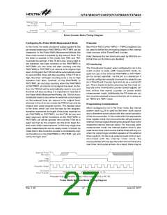
The 16-bit Timer/Event Counter have contained both
low byte and high byte timer registers, accessing these
registers is carried out in a specific way. It must be noted
that when using instructions to preload data into the low
byte register, namely TMR0L, the data will only be
placed in a low byte buffer and not directly into the low
byte register. The actual transfer of the data into the low
byte register is only carried out when a write to its asso-
ciated high byte register, namely TMR0H, is executed.
On the other hand, using instructions to preload data
into the high byte timer register will result in the data be-
ing directly written to the high byte register. At the same
time the data in the low byte buffer will be transferred
into its associated low byte register. For this reason,
when preloading data into the 16-bit timer registers, the
low byte should be written first. It must also be noted that
to read the contents of the low byte register, a read to the
Timer Registers - TMR0H/TMR0L, TMR1, TMR2
The timer registers are special function registers located
in the special purpose Data Memory and is the place
where the actual timer value is stored. For the 8-bit timer,
this register is known as Timer/Event Counter 1/2. In the
case of the 16-bit timer, a pair of 8-bit registers are re-
quired to store the 16-bit timer values. These are known
as TMR1L/TMR1H. The value in the timer registers in-
creases by one each time an internal clock pulse is re-
ceived or an external transition occurs on the external
timer pin. The timer will count from the initial value loaded
by the preload register to the full count of FFH for the 8-bit
timer or FFFFH for the 16-bit timers, at which point the
timer overflows and a timer internal interrupt signal is
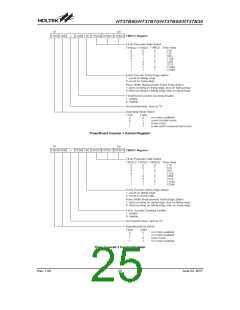
Timer/Event Counter 0 Control Register
Rev. 1.00
24
June 22, 2017

 HOLTEK [ HOLTEK SEMICONDUCTOR INC ]