HT37B90/HT37B70/HT37B50/HT37B30
RC/F Interrupt
Timer/Event Counter Interrupts
The external RC Oscillation Converter interrupt is initial-
ized by setting the external RC Oscillation Converter in-
terrupt request flag, RCOCF; bit 5 of INTCH. This is
caused by a Timer A or Timer B overflow. When the in-
terrupt is enabled, and the stack is not full and the
RCOCF bit is set, a subroutine call to location ²14H² will
occur.
For a timer generated internal interrupt to occur, the cor-
responding internal interrupt enable bit must be first set.
Each device have two internal Timer Counters, the
Timer/Event Counter 0 interrupt enable is bit 2 of the
INTC register and known as ET0I, the Timer/Event Coun-
ter 1 interrupt enable is bit 3 of the INTC register and
known as ET1I and the Timer Counter 2 interrupt enable
is bit 0 of the INTCH register and is known as ET2I. An
actual Timer/Event Counter interrupt will be initialized
when the Timer/Event Counter interrupt request flag is
set, caused by a timer overflow. Each device has two tim-
ers, the Timer/Event Counter 0 request flag is bit 5 of the
INTC register and known as T0F, the Timer/Event Coun-
ter 1 request flag is bit 6 of the INTC register and known
as T1F, and the Timer Counter 2 request flag is bit 4 of the
INTCH register and is known as T2F.
The related interrupt request flag, RCOCF, will be reset
and the EMI bit cleared to disable further interrupts.
ADPCM Interrupt
The internal ADPCM interrupt is initialized by setting the
ADPCM interrupt request flag (ADPCMF: bit 6, CH0F:
bit 3 and CH1F: bit 7 of INTCH).The CH0F and CH1F
set by ADR0 or ADR1 empty respectively. The
ADPCMF is set by ADR0 or ADR1 empty immediately.
When the interrupt is enabled, and the stack is not full
and the T0F bit is set, a subroutine call to location 18H
will occur. The related interrupt request ADPCMF and
CH0F/CH1F flag will be reset and the EMI bit cleared to
disable further interrupts.
When the master interrupt global enable bit is set, the
stack is not full and the corresponding timer interrupt en-
able bit is set, an internal interrupt will be generated
when the corresponding timer overflows. Each device
have two internal Timer/Event Counters, a subroutine
call to location 08H will occur for Timer/Event Counter 0,
a subroutine call to location 0CH for Timer/Event Coun-
ter 1, a subroutine call to location 10H for Timer Counter
2. After entering the timer interrupt execution routine,
the corresponding timer interrupt request flag, either,
T0F, T1F or T2F will be reset and the EMI bit will be
cleared to disable other interrupts.
Programming Considerations
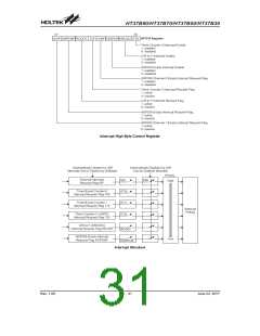
The interrupt request flags T0F, T1F, T2F, ADPCMF,
CH0F, CH1F, together with the interrupt enable bits
ET0I, ET1I, ET2I, EADPCM, form the interrupt control
registers INTC, INTCH which are located in the Data
Memory. By disabling the interrupt enable bits, a re-
quested interrupt can be prevented from being serviced,
however, once an interrupt request flag is set, it will re-
main in this condition in the INTC or INTCH register until
the corresponding interrupt is serviced or until the re-
quest flag is cleared by a software instruction. It is rec-
ommended that programs do not use the ²CALL
subroutine² instruction within the interrupt subroutine.
Interrupts often occur in an unpredictable manner or
need to be serviced immediately in some applications. If
only one stack is left and the interrupt is not well con-
trolled, the original control sequence will be damaged
once a ²CALL subroutine² is executed in the interrupt
subroutine.
UART Interrupt
The device contain an internal UART function share with
Timer Counter 2. It_s corresponding UART interrupt
work by enabled UART function enable configuration
option, which is bit 7 of the UART function enable config-
uration option. An actual UART interrupt will be initial-
ized when the UART interrupt request flag T2F is set,
which is bit 0 of the INTCH register. When the master in-
terrupt global bit is set, the stack is not full and the corre-
sponding ET2I interrupt enable bit is set, a UART
internal interrupt will be generated when a UART inter-
rupt request occurs. This will create a subroutine call to
its corresponding vector location 010H. When a UART
internal interrupt occurs, the interrupt request flag T2F
All of these interrupts have the capability of waking up
the processor when in the Power Down Mode. Only the
Program Counter is pushed onto the stack. If the con-
tents of the register or status register are altered by the
interrupt service program, which may corrupt the de-
sired control sequence, then the contents should be
saved in advance.
will be reset and the EMI bit cleared to disable other in-
terrupts. There are various UART conditions, which can
generate a UART interrupt, such as certain data trans-
mission and reception conditions, overrun errors as well
as an address detect condition. These conditions are re-
flected by various flags within the UART_s status regis-
ter, known as the RS232C register. Various bits in the
UART_s setup register, BRGR, determine if these flags
can generate a UART interrupt signal. More details on
these two registers and how they influence the opera-
tion of the UART interrupt can be found in the UART
section of the datasheet.
Rev. 1.00
32
June 22, 2017

 HOLTEK [ HOLTEK SEMICONDUCTOR INC ]