HT37B90/HT37B70/HT37B50/HT37B30
high byte register must first be executed to latch the con-
tents of the low byte buffer into its associated low byte
register. After this has been done, the low byte register
can be read in the normal way. Note that reading the low
byte timer register will only result in reading the previ-
ously latched contents of the low byte buffer and not the
actual contents of the low byte timer register.
determined by bits PSC0~PSC2 of the TMR1C~
TMR2C register. The timer-on bit, TON must be set high
to enable the timer to run. Each time an internal clock
high to low transition occurs, the timer increments by
one. When the timer is full and overflows, the timer will
be reset to the value already loaded into the preload reg-
ister and continue counting. If the timer interrupt is en-
abled, an interrupt signal will also be generated. The
timer interrupt can be disabled by ensuring that the
ET0I~ET2I bit in the INTC and INTCH registers is
cleared to zero. It should be noted that a timer overflow
is one of the wake-up sources.
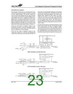
Timer Control Registers - TMR0C, TMR1C, TMR2C
The Timer/Event Counters0/1 enable them to operate in
three different modes. the options of which are deter-
mined by the contents of their respective control regis-
ter. There are four timer control registers, known as
TMR0C, TMR1C and TMR2C. It is the timer control reg-
ister together with its corresponding timer registers that
control the full operation of the Timer/Event Counters.
Before the timers can be used, it is essential that the ap-
propriate timer control register is fully programmed with
the right data to ensure its correct operation, a process
that is normally carried out during program initialization.
To choose which of the three modes the timer is to oper-
ate in, either in the timer mode, the event counting mode
or the pulse width measurement mode, bits 7 and 6 of
the Timer Control Register, which are known as the bit
pair T0M1/T0M0, T1M1/T1M0 respectively, depending
upon which timer is used, must be set to the required
logic levels. The timer-on bit, which is bit 4 of the Timer
Control Register and known as T0ON, T1ON or T2ON,
depending upon which timer is used, provides the basic
on/off control of the respective timer. Setting the bit high
allows the counter to run, clearing the bit stops the coun-
ter. If the timer is in the event count or pulse width mea-
surement mode, the active transition edge level type is
selected by the logic level of bit 3 of the Timer Control
Register which is known as T0E, T1E or T2E, depend-
ing upon which timer is used.
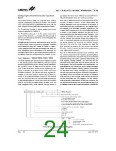
Configuring the Event Counter Mode
In this mode, two number of externally changing logic
events, occurring on external pin PA6/TMR0 or
PA7/TMR1, can be recorded by the internal timer. For
the timer to operate in the event counting mode, bits
TM1 and TM0 of the TMR0C or TMR1C registers must
be set to 0 and 1 respectively. The timer-on bit, TON
must be set high to enable the timer to count. With TE
low, the counter will increment each time the PA6/TMR0
or PA7/TMR1 pin receives a low to high transition. If the
TE bit is high, the counter will increment each time
PA6/TMR0 or PA7/TMR1 pin receives a high to low tran-
sition. As in the case of the other two modes, when the
counter is full and overflows, the timer will be reset to the
value already loaded into the preload register and con-
tinue counting. If the timer interrupt is enabled, an inter-
rupt signal will also be generated.
The timer interrupt can be disabled by ensuring that the
ETI bit in the INTC and INTCH registers is cleared to
zero. To ensure that the external pin PA6/TMR0 or
PA7/TMR1 is configured to operate as an event counter
input pin, two things have to happen. The first is to en-
sure that the TM0 and TM1 bits place the timer/event
counter in the event counting mode, the second is to en-
sure that the share pin TMR0 or TMR1 are selected by
option. It should be noted that a timer overflow is one of
the wake-up sources. Also in the Event Counting mode,
the Timer/Event Counter will continue to record exter-
nally changing logic events on the timer input pin, even if
the microcontroller is in the Power Down Mode. As a re-
sult when the timer overflows it will generate a wake-up
and if the interrupts are enabled also generate a timer
interrupt signal.
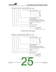
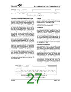
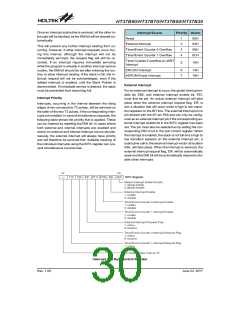
Configuring the Timer Mode
In this mode, the timer can be utilized to measure fixed
time intervals, providing an internal interrupt signal each
time the counter overflows. To operate in this mode, bits
TM1 and TM0 of the TMR0C~TMR2C register must be
set to 1 and 0 respectively. In this mode, the internal
clock is used as the timer clock. The input clock fre-
quency of 16 bit timer to the timer is fOSC/8 and RC12K,
selected by TMR0C.5. The input clock frequency of 8 bit
timer to the timer is Fosc divided by the value pro-
grammed into the timer prescaler, the value of which is
Timer Mode Timing Diagram
Rev. 1.00
26
June 22, 2017

 HOLTEK [ HOLTEK SEMICONDUCTOR INC ]