HT36B0
The Timer/Event Counter 1 operates in the same man-
ner as Timer/Event Counter 0.
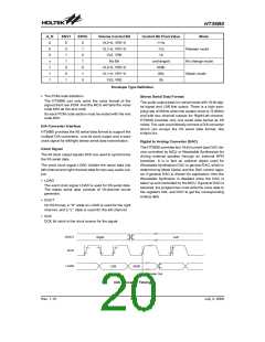
bits equal to one, once the TMR has received a transient
from low to high (or high to low; if the TE bit is 0) it will
start counting until the TMR returns to the original level
and resets the TON. The measured result will remain in
the even if the activated transient occurs again. In other
words, only one cycle measurements can be done. Until
setting the TON, the cycle measurement will function
again as long as it receives further transient pulse. Note
that, in this operating mode, the timer/event counter
starts counting not according to the logic level but ac-
cording to the transient edges. In the case of counter
overflows, the counter is reloaded from the timer/event
counter preload register and issues the interrupt request
just like the other two modes.
The TMR0C is the Timer/Event Counter 0 control regis-
ter, which defines the Timer/Event Counter 0 options.
The Timer/Event Counter 1 has the same options with
Timer/Event Counter 0 and is defined by TMR1C.
The Timer/event Counter control registers define the op-
erating mode, counting enable or disable and active
edge.
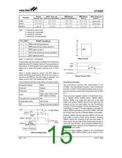
The TM0, TM1 bits define the operating mode. The
Event count mode is used to count external events,
which means the clock source comes from an external
(TMR) pin. The Timer mode functions as a normal timer
with the clock source coming from the instruction clock.
The pulse width measurement mode can be used to
count the high or low level duration of the external signal
(TMR). The counting is based on the instruction clock.
To enable the counting operation, the Timer ON bit (TON;
bit 4 of TMR0C/TMR1C) should be set to 1. In the pulse
width measurement mode, the TON will be cleared auto-
matically after the measurement cycle is completed. But
in the other two modes the TON can only be reset by in-
struction. The overflow of the timer/event counter is one
of the wake-up sources. No matter what the operation
mode is, writing a 0 to ET0I/ET1I can disable the corre-
sponding interrupt service.
In the Event count or Timer mode, once the timer/event
counter starts counting, it will count from the current
contents in the timer/event counter to FFFFH. Once
overflow occurs, the counter is reloaded from the
Timer/Event Counter Preload register and simulta-
neously generates the corresponding interrupt request
flag (T0F/T1F; bit 5/6 of INTC).
In the case of timer/event counter OFF condition, writing
data to the Timer/event Counter Preload register will
also reload that data to the timer/event counter. But if
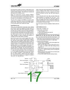
In pulse width measurement mode with the TON and TE
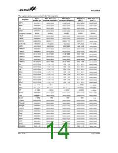
Bit No.
Label
Function
0~2
¾
Unused bit, read as ²0²
Define the TMR active edge of Timer/Event Counter 0
(0=active on low to high; 1=active on high to low)
3
TE
Enable/disable timer counting
(0=disable; 1=enable)
4
5
TON
¾
Unused bit, read as ²0²
Defines the operating mode
01=Event count mode (External clock)
10=Timer mode (Internal clock)
11=Pulse width measurement mode
00=Unused
6
7
TM0
TM1
TMR0C(0EH) / TMR1C(11H) Register
D
a
t
a
B
u
s
S
y
s
t
e
m
C
l
o
c
k
/
8
T
M
1
R
e
l
o
a
d
T
M
0
T
i
m
e
r
/
e
v
e
n
t
C
o
u
n
t
e
r
0
P
r
e
l
o
a
d
R
e
g
i
s
t
e
r
G
N
D
T
E
T
i
m
e
r
/
e
v
e
n
t
P
u
l
s
e
W
i
n
d
t
h
O
v
e
r
f
l
o
w
T
M
1
C
o
u
n
t
e
r
0
M
e
a
s
u
r
e
m
e
n
t
T
o
I
n
t
e
r
r
u
p
t
T
M
0
M
o
d
e
C
o
t
r
o
l
T
O
N
L
o
w
B
y
t
e
B
u
f
f
e
r
Timer/Event Counter 0/1
Rev. 1.10
16
July 3, 2008
图片预览")
 HOLTEK [ HOLTEK SEMICONDUCTOR INC ]