HT36B0
the latter of the two T2 pulses, if the corresponding inter-
rupts are enabled. In the case of simultaneous requests
the priorities in the following table apply. These can be
masked by resetting the EMI bit.
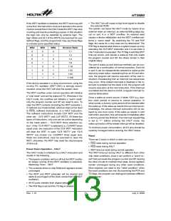
timing sensitive operations where accurate oscillator
frequency is desired.
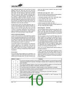
On the other hand, if the crystal oscillator is selected, a
crystal across OSC1 and OSC2 is needed to provide the
feedback and phase shift required for the oscillator, and
no other external components are required. A resonator
may be connected between OSC1 and OSC2 to replace
the crystal and to get a frequency reference, but two ex-
ternal capacitors in OSC1 and OSC2 are required.
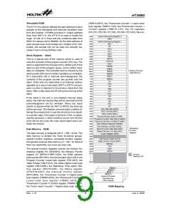
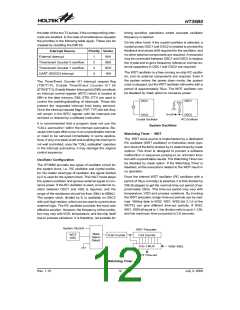
Interrupt Source
External Interrupt
Priority Vector
1
2
3
4
04H
08H
0CH
10H
Timer/event Counter 0 overflow
Timer/event Counter 1 overflow
UART (RS232) Interrupt
The WDT oscillator is a free running on-chip RC oscilla-
tor, and no external components are required. Even if
the system enters the power down mode, the system
clock is stopped, but the WDT oscillator still works with a
period of approximately 78ms. The WDT oscillator can
be disabled by mask option to conserve power.
The Timer/Event Counter 0/1 interrupt request flag
(T0F/T1F), Enable Timer/Event Counter 0/1 bit
(ET0I/ET1I), Enable Master Interrupt bit (EMI) constitute
an interrupt control register (INTC) which is located at
0BH in the data memory. EMI, ET0I, ET1I are used to
control the enabling/disabling of interrupts. These bits
prevent the requested interrupt from being serviced.
Once the interrupt request flags (T0F, T1F) are set, they
will remain in the INTC register until the interrupts are
serviced or cleared by a software instruction.
O
S
C
1
O
S
C
1
V
D
D
f
S
Y
S
/
8
O
S
C
2
O
S
C
2
C
r
y
s
t
a
l
O
s
c
i
l
l
a
t
o
r
R
C
O
s
c
i
l
l
a
t
o
r
It is recommended that a program does not use the
²CALL subroutine² within the interrupt subroutine. Be-
cause interrupts often occur in an unpredictable manner
or need to be serviced immediately in some applica-
tions, if only one stack is left and enabling the interrupt is
not well controlled, once the ²CALL subroutine² operates
in the interrupt subroutine, it may damage the original
control sequence.
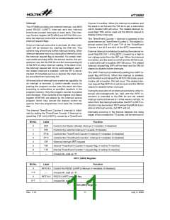
System Oscillator
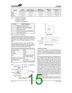
Watchdog Timer - WDT
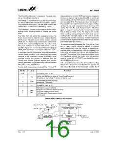
The WDT clock source is implemented by a dedicated
RC oscillator (WDT oscillator) or instruction clock (sys-
tem clock of the MCU divided by 4), determined by mask
options. This timer is designed to prevent a software
malfunction or sequence jumping to an unknown loca-
tion with unpredictable results. The Watchdog Timer can
be disabled by mask option. If the Watchdog Timer is
disabled, all the executions related to the WDT result in
no operation.
Oscillator Configuration
The HT36B0 provides two types of oscillator circuit for
the system clock, i.e., RC oscillator and crystal oscilla-
tor. No matter what type of oscillator, the signal divided
by 2 is used for the system clock. The HALT mode stops
the system oscillator and ignores external signal to con-
serve power. If the RC oscillator is used, an external re-
sistor between OSC1 and VSS is required, and the
range of the resistance should be from 30kW to 680kW.
The system clock, divided by 8, is available on OSC2
with pull-high resistor, which can be used to synchronize
external logic. The RC oscillator provides the most cost
effective solution. However, the frequency of the oscilla-
tion may vary with VDD, temperature, and the chip itself
due to process variations. It is therefore, not suitable for
Once the internal WDT oscillator (RC oscillator with a
period of 78ms normally) is selected, it is first divided by
256 (8-stages) to get the nominal time-out period of ap-
proximately 20ms. This time-out period may vary with
temperature, VDD and process variations. By invoking
the WDT prescaler, longer time-out periods can be real-
ized. Writing data to WS2, WS1, WS0 (bit 2,1,0 of the
WDTS) can give different time-out periods. If WS2,
WS1, WS0 all equal to 1, the division ratio is up to 1:128,
and the maximum time-out period is 2.6 seconds.
S
y
s
t
e
m
C
l
o
c
k
/
8
W
D
T
P
r
e
s
c
a
l
e
r
M
a
s
k
W
D
T
8
-
b
i
t
C
o
u
n
t
e
r
7
-
b
i
t
C
o
u
n
t
e
r
O
p
t
i
o
n
O
S
C
S
e
l
e
c
t
8
-
t
o
-
1
M
U
X
W
S
0
~
W
S
2
W
D
T
T
i
m
e
-
o
u
t
Watchdog Timer
Rev. 1.10
12
July 3, 2008
图片预览")
 HOLTEK [ HOLTEK SEMICONDUCTOR INC ]