HT36B0
·
The HALT pin will output a high level signal to disable
the external ROM.
If the WDT oscillator is disabled, the WDT clock may still
come from the instruction clock and operate in the same
manner except that in the HALT state the WDT may stop
counting and lose its protecting purpose. In this situation
the logic can only be restarted by external logic. The
high nibble and bit 3 of the WDTS are reserved for user
defined flags, and the programmer may use these flags
to indicate some specified status.
The system can leave the HALT mode by means of an
external reset, an interrupt, an external falling edge sig-
nal on port A or a WDT overflow. An external reset
causes a device initialization and the WDT overflow per-
forms a ²warm reset². By examining the TO and PDF
flags, the cause for a chip reset can be determined. The
PDF flag is cleared when there is a system power-up or by
executing the CLR WDT instruction and it is set when a
HALT instruction is executed. The TO flag is set if the WDT
time-out occurs, and causes a wake-up that only resets
the program counter and SP, the others remain in their
original status.
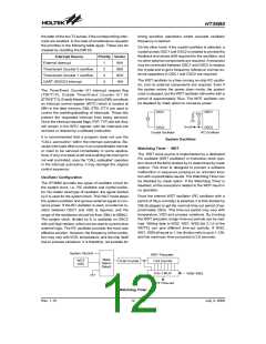
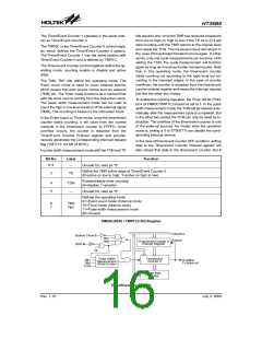
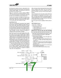
WS2
WS1
WS0
Division Ratio
0
0
0
0
1
1
1
1
0
0
1
1
0
0
1
1
0
1
0
1
0
1
0
1
1:1
1:2
1:4
1:8
The port A wake-up and interrupt methods can be con-
sidered as a continuation of normal execution. Each bit
in port A can be independently selected to wake-up the
device by mask option. Awakening from an I/O port stim-
ulus, the program will resume execution of the next in-
struction. If awakening from an interrupt, two sequences
may occur. If the related interrupts is disabled or the in-
terrupts is enabled but the stack is full, the program will
resume execution at the next instruction. If the interrupt
is enabled and the stack is not full, a regular interrupt re-
sponse takes place.
1:16
1:32
1:64
1:128
If the device operates in a noisy environment, using the
on-chip RC oscillator (WDT OSC) is strongly recom-
mended, since the HALT will stop the system clock.
The WDT overflow under normal operation will initialize
a ²chip reset² and set the status bit TO. Whereas in the
HALT mode, the overflow will initialize a ²warm reset²
only the program counter and SP are reset to zero. To
clear the WDT contents (including the WDT prescaler ),
3 methods are implemented; external reset (a low level
to RES), software instructions, or a HALT instruction.
The software instructions include CLR WDT and the
other set - CLR WDT1 and CLR WDT2. Of these two
types of instructions, only one can be active depending
on the mask option - ²CLR WDT times selection op-
tion². If the ²CLR WDT² is selected (i.e. CLRWDT times
equal one), any execution of the CLR WDT instruction
will clear the WDT. In case ²CLR WDT1² and ²CLR
WDT2² are chosen (i.e. CLRWDT times equal two),
these two instructions must be executed to clear the
WDT; otherwise, the WDT may reset the chip because
of time-out.
Once a wake-up event occurs, it takes 1024 tSYS (sys-
tem clock period) to resume to normal operation. In
other words, a dummy cycle period will be inserted after
the wake-up. If the wake-up results from an interrupt ac-
knowledge, the actual interrupt subroutine will be de-
layed by one more cycle. If the wake-up results in next
instruction execution, this will execute immediately after
a dummy period has finished. If an interrupt request flag
is set to ²1² before entering the HALT mode, the
wake-up function of the related interrupt will be disabled.
To minimize power consumption, all I/O pins should be
carefully managed before entering the HALT status.
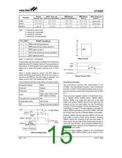
Reset
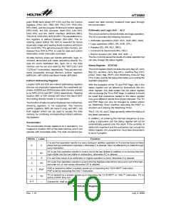
There are 3 ways in which a reset can occur:
·
·
·
RES reset during normal operation
RES reset during HALT
Power Down Operation - HALT
WDT time-out reset during normal operation
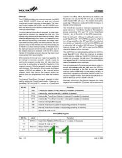
The HALT mode is initialized by a HALT instruction and
results in the following...
The WDT time-out during HALT is different from other
chip reset conditions, since it can perform a ²warm re -
set² that just resets the program counter and SP, leaving
the other circuits to maintain their state. Some registers
remain unchanged during any other reset conditions.
Most registers are reset to the ²initial condition² when
the reset conditions are met. By examining the PDF and
TO flags, the program can distinguish between different
²chip resets².
·
The system oscillator will turn off but the WDT oscilla-
tor keeps running (If the WDT oscillator is selected).
Watchdog Timer - WDT
·
·
The contents of the on-chip RAM and registers remain
unchanged
The WDT and WDT prescaler will be cleared and
starts to count again (if the clock comes from the WDT
oscillator).
·
·
All I/O ports maintain their original status.
The PDF flag is set and the TO flag is cleared.
Rev. 1.10
13
July 3, 2008
图片预览")
 HOLTEK [ HOLTEK SEMICONDUCTOR INC ]