HT36B0
·
·
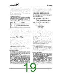
Waveform format definition
CH3~0 channel number selection
The HT36B0 has a built-in 16 output channels and
CH3~0 is used to define which channel is selected.
When this register is written to, the wavetable synthe-
sizer will automatically output the dedicated PCM code.
So this register is also used as a start playing key and it
has to be written to after all the other wavetable function
registers are already defined.
The HT36B0 accepts two waveform formats to en-
sure a more economical data space. WBS is used to
define the sample format of each PCM code.
¨
¨
WBS=0 means the sample format is 8-bit
WBS=1 means the sample format is 12-bit
The 12-bit sample format allocates location to each
sample data. Please refer to the waveform format
statement as shown below.
·
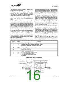
Change parameter selection
These two bits, VM and FR, are used to define which
register will be updated on this selected channel. There
are two modes that can be selected to reduce the pro-
cess of setting the register. Please refer to the state-
ments of the following table:
8
-
B
i
t
1
B
2
B
3
B
4
B
5
B
6
B
7
B
8
B
A
1
s
a
m
p
l
i
n
g
d
a
t
a
c
o
d
e
;
B
m
e
a
n
s
o
n
e
d
a
t
a
b
y
t
e
.
1
2
-
B
i
t
H
1
M
1
L
2
L
2
H
2
M
3
H
3
M
3
L
VM
0
FR
0
Function
A
s
a
m
p
l
i
n
g
d
a
t
a
c
o
d
e
Update all the parameter
Only update the frequency number
Only update the volume
0
1
N
o
t
e
:
"
1
H
"
H
i
g
h
N
i
b
b
l
e
"
"
1
1
M
L
"
M
i
d
d
l
e
N
i
b
b
l
e
1
0
"
L
o
w
N
i
b
b
l
e
·
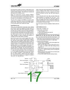
Output frequency definition
Waveform Format
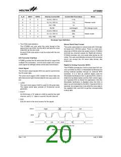
Repeat number definition
The data on BL3~0 and FR11~0 are used to define the
output speed of the PCM file, i.e. it can be used to gen-
erate the tone scale. When the FR11~0 is 800H and
BL3~0 is 6H, each sample data of the PCM code will be
sent out sequentially.
·
The repeat number is used to define the address
which is the repeat point of the sample. When the
repeat number is defined, it will be output from the
start code to the end code once and always output
the range between the repeat address to the end
code (80H) until the volume become close.
When the fOSC is 12.8MHz, the formula of a tone fre-
quency is:
50kHz
FR11~ 0
(17- BL3~0)
fOUT= fRECORD
´
´
SR
2
The RE14~0 is used to calculate the repeat address
of the PCM code. The process for setting the
RE14~0 is to write the 2¢s complement of the repeat
length to RE14~0, with the highest carry ignored.
The HT36B0 will get the repeat address by adding
the RE14~0 to the address of the end code, then
jump to the address to repeat this range.
where fOUT is the output signal frequency, fRECORD and
SR is the frequency and sampling rate on the sample
code, respectively.
So if a voice code of C3 has been recorded which has
the fRECORD of 261Hz and the SR of 11025Hz, the tone
frequency (fOUT) of G3: fOUT=196Hz.
Can be obtained by using the fomula:
·
Left and Right volume control
50kHz
FR11~ 0
(17- BL3~0)
The HT36B0 provides the left and right volume con-
trol independently. The left and right volume are
controlled by VL9~0 and VR9~0 respectively. The
chip provides 1024 levels of controllable volume,
the 000H is the maximum and 3FFH is the minimum
output volume.
196Hz= 261Hz ´
´
11025Hz
2
A pair of the values FR11~0 and BL3~0 can be deter-
mined when the fOSC is 12.8MHz.
·
Start address definition
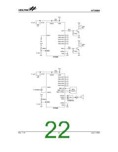
The HT36B0 provides two address types for extended
use, one is the program ROM address which is program
counter corresponding with PF value, the other is the
start address of the PCM code.
·
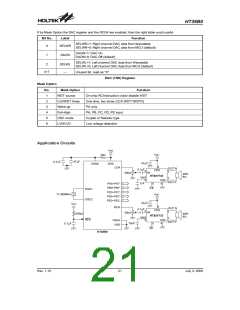
Envelope type definition
The HT36B0 provides a function to easily program
the envelope by setting the data of ENV1~0 and
A_R. It forms a vibrato effect by a change of the
volume to attach and release alternately.
The ST15~0 is used to define the start address of each
PCM code and reads the waveform data from this loca-
tion. The HT36B0 provides 16 input data lines from
WA15~0, the ST15~0 is used to locate the major 16 bits
i.e. WA15~5 and the undefined data from WA4~0 is al-
ways set as 00000b. In other words, the WA15~0=
ST15~0 ´ 25. So each PCM code has to be located at a
multiple of 32. Otherwise, the PCM code will not be read
out correctly because it has a wrong start code.
The A_R signal is used to define the volume change
in attach mode or release mode and ENV1~0 is
used to define which volume control bit will be
changeable. On the attach mode, the control bits
will be sequentially signaled down to 0. On the re-
lease mode, the control bits will be sequentially sig-
naled up to 1. The relationship is shown in the
following table.
Rev. 1.10
19
July 3, 2008
图片预览")
 HOLTEK [ HOLTEK SEMICONDUCTOR INC ]