HT36B0
Interrupt
Counter 0 overflow. When the interrupt is enabled, and
the stack is not full and the T0F bit is set, a subroutine
call to location 08H will occur. The related interrupt re-
quest flag (T0F) will be reset and the EMI bit cleared to
disable further interrupts.
The HT36B0 provides one external interrupt, one MIDI
used RS232 (UART) interrupt and two internal
timer/event counter interrupts on each bank. The Inter-
rupt Control register (INTC;0BH and INTCH;2EH) con-
tains the interrupt control bits as enable/disable and the
interrupt request flags.
The Timer/Event Counter 1 interrupt is operated in the
same manner as Timer/Event Counter 0. The related in-
terrupt control bits ET1I and T1F of the Timer/Event
Counter 1 are bit 3 and bit 6 of the INTC respectively.
Once an interrupt subroutine is serviced, all other inter-
rupts will be blocked (by clearing the EMI bit). This
scheme may prevent any further interrupt nesting. Other
interrupt requests may occur during this interval but only
the interrupt request flag is recorded. If a certain inter-
rupt needs servicing within the service routine, the pro-
grammer may set the EMI bit and the corresponding bit
of the INTC to allow interrupt nesting. If the stack is full,
the interrupt request will not be acknowledged, even if
the related interrupt is enabled, until the SP is decre-
mented. If immediate service is desired, the stack must
be prevented from becoming full.
External interrupt is initialized by setting the external re-
quest flag (EEI; bit 1 of the INTC), caused by a high-to
low voltage pulse from the INT pad. When the interrupt
is enabled, and the stack is not full and the EEI bit is set,
a subroutine call to location 04H will occur. The related
interrupt request flag (EIF) will be reset and the EMI bit
cleared to disable further interrupts.
The UART interrupt is initialized by setting the UART re-
quest flag (INTCH.0). When the interrupt is enabled,
and the stack is not full and the INTCH.0 bit is set, a sub-
routine call to location 10H will occur. The related inter-
rupt request flag (INTCH.4) will be reset and the EMI bit
cleared to disable further interrupts.
All these kinds of interrupt have a wake-up capability. As
an interrupt is serviced, a control transfer occurs by
pushing the program counter onto the stack and then
branching to subroutines at specified locations in the
program memory. Only the program counter is pushed
onto the stack. If the contents of the register and Status
register (STATUS) are altered by the interrupt service
program which may corrupt the desired control se-
quence, then the programmer must save the contents
first.
During the execution of an interrupt subroutine, other in-
terrupt acknowledgments are held until the RETI in-
struction is executed or the EMI bit and the related
interrupt control bit are set to 1 (if the stack is not full). To
return from the interrupt subroutine, the RET or RETI in-
struction may be invoked. RETI will set the EMI bit to en-
able an interrupt service, but RET will not.
The internal Timer/Event Counter 0 interrupt is initial-
ized by setting the Timer/Event Counter 0 interrupt re-
quest flag (T0F; bit 5 of INTC), caused by a Timer/Event
Interrupts occurring in the interval between the rising
edges of two consecutive T2 pulses, will be serviced on
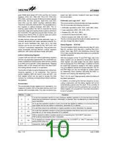
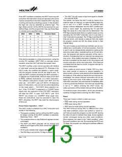
Bit No.
Label
EMI
EEI
Function
0
1
2
3
4
5
6
7
Controls the Master (Global) interrupt (1=enabled; 0=disabled)
Controls the external interrupt (1=enable; 0=disable)
Controls the Timer/Event Counter 0 interrupt (1=enabled; 0=disabled)
Controls the Timer/Event Counter 1 interrupt (1=enabled; 0=disabled)
External interrupt (INT) request
ET0I
ET1I
EIF
T0F
T1F
¾
Internal Timer/Event Counter 0 request flag (1=active; 0=inactive)
Internal Timer/Event Counter 1 request flag (1=active; 0=inactive)
Unused bit, read as ²0²
INTC (OBH) Register
Bit No.
0
Label
Function
INTCH.0 Control the RS232 (UART) Interrupt (1=enabled; 0=disabled)
1~3
4
¾
Unused bit, read as ²0²
INTCH.4 RS232 (UART) request flag
5~7
¾
Unused bit, read as ²0²
INTCH (2EH) Register
Rev. 1.10
11
July 3, 2008
图片预览")
 HOLTEK [ HOLTEK SEMICONDUCTOR INC ]