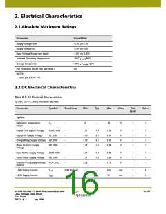
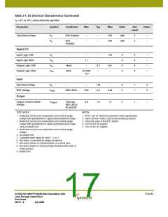
Table 2-1: DC Electrical Characteristics (Continued)
TA = 0°C to 70°C, unless otherwise specified.
Parameter
Symbol
Conditions
Min
Typ
Max
Units
Test
Notes
Level
Total Device Power
PD
PD
SDO Enabled
–
–
–
–
550
450
mW
mW
3
3
–
–
SDO
Disabled
Digital I/O
Input Logic LOW
Input Logic HIGH
Output Logic LOW
Output Logic HIGH
VIL
–
–
2.1
–
–
–
0.8
–
V
V
V
V
4
4
4
4
–
–
–
–
VIH
VOL
VOH
–
+8mA
-8mA
0.2
–
0.4
–
IO_VDD
- 0.4
Input
Input Bias Voltage
RSET Voltage
VB
–
–
1.45
0.6
–
V
V
1
1
2
3
VRSET
RSET=281Ω
0.54
0.66
Output
Output Common Mode
Voltage
VCMOUT
75Ω load,
RSET=281Ω,
SD and HD
0.8
1.0
1.2
V
1
–
TEST LEVELS
NOTES
1. Production test at room temperature and nominal supply
voltage with guardbands for supply and temperature ranges.
2. Production test at room temperature and nominal supply
voltage with guardbands for supply and temperature ranges
using correlated test.
1. All DC and AC electrical parameters within specification.
2. Input common mode is set by internal biasing resistors.
3. Set by the value of the RSET resistor.
4. Sum of all 1.8V supplies.
5. Sum of all 3.3V supplies.
3. Production test at room temperature and nominal supply
voltage.
4. QA sample test.
5. Calculated result based on Level 1, 2, or 3.
6. Not tested. Guaranteed by design simulations.
7. Not tested. Based on characterization of nominal parts.
8. Not tested. Based on existing design/characterization data of
similar product.
9. Indirect test.
GS1559 HD-LINX™ II Multi-Rate Deserializer with
Loop-Through Cable Driver
Data Sheet
17 of 71
30572 - 8
July 2008

 GENNUM [ GENNUM CORPORATION ]