FA13842, 13843, 13844, 13845
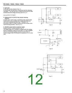
4. Soft start
A soft-start circuit is shown in Fig. 15.
An aproximate soft-start time is determined with the following
calculation. This soft-start time is defined as the time the ISNS
terminal threshold voltage increases from 0V to 1V.
8
4
REF
OSC
tsoft-start [ms]=4.3•C9[µF]
1mA
5. Suppression of noise at the current sensing
terminal
2R
+
R17
2
1
D7
ER AMP
1MΩ
As each cycle current value is monitored in the current mode
control, there is the possibility that a malfunction will occur
even with a relatively low noise level. Therefore, it is
necessary to add a CR filter to reduce the level of noise at the
current sensing terminal. (See Fig. 16.)
1R
D8
C9
5
Fig. 15
6. ON/OFF circuit with an external signal
A typical ON/OFF circuit is shown in Fig. 17.
The output stage (OUT terminal) is enabled when the voltage
at the FB terminal is reduced to less than 2.0V and is disabled
when the FB terminal voltage increases to more than 3V.
Set the voltage of the FB terminal at a maximum of 5.3V in this
case.
DB
~
T1
+
+
C1
AC INPUT
~
MOSFET
6
3
FA13842
R18
Rs
C10
Fig. 16
7
8
REF
30V
4
OSC
2R
R19
+
2
1
ER AMP
ON/OFF signal
1R
Tr6
5
Fig. 17
12

 FUJI [ FUJI ELECTRIC ]