FA13842, 13843, 13844, 13845
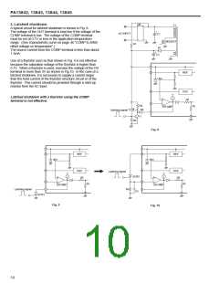
3. Latched shutdown
DB
~
T1
+
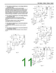
A typical circuit for latched shutdown is shown in Fig. 8.
The voltage of the OUT terminal is kept low if the voltage of the
COMP terminal is low. The voltage of the COMP terminal
must be set at 0.7V or less in the application temperature
range. (See characteristic curve on page 46 ”COMP to ISNS
offset voltage vs temperature”.)
+
AC INPUT
C1
~
MOSFET
R1
D1
The source current from the COMP terminal is less than about
1.3mA.
+
C2
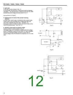
Use of a thyristor such as that shown in Fig. 9 is not effective
because the saturation voltage of the thyristor is higher than
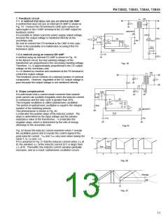
0.7V. When a thyristor is used, increase the voltage of the FB
terminal to more than 3V as shown in Fig.10. In the case of a
latched shutdown, it is necessary to supply a current larger
than the hold current of the thyristor structure circuit or of the
thyristor. This current should be provided through a start-up
resistor from the AC input.
7
8
REF
30V
4
OSC
2R
Latched shutdown with a thyristor using the COMP
terminal is not effective.
+
2
1
R4
D4
1R
ER AMP
Tr2
Latching signal
5
Tr1
R3
Fig. 8
7
7
8
8
REF
OSC
REF
30V
30V
4
4
OSC
2R
Latching signal
SCR2
C5
2R
+
+
2
1
2
1R
1R
ER AMP
ER AMP
Latching signal
R5
1
5
5
SCR1
Fig. 9
Fig. 10
10

 FUJI [ FUJI ELECTRIC ]