FT2232C Dual USB UART / FIFO I.C.
9.8 Fast Opto-Isolated Serial Interface Mode Signal Description and Configuration
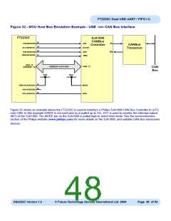
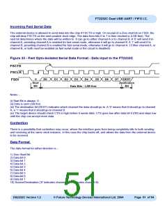
Fast Opto-Isolated Serial Interface Mode provides a method of communicating with an external device over USB using
4 wires that can have opto-isolators in their path, thus providing galvanic isolation between systems. If either channel
A or channel B are enabled in fast opto-isolated serial mode then the pins on channel B are switched to the fast serial
interface configuration. The I/O interface for fast serial mode is always on channel B, even if both channels are being
used in this mode. An address bit is used to determine the source or destination channel of the data. It therefore
makes sense to always use at least channel B or both for fast serial mode, but not A own its own.
When either Channel B or Both Channel A and B are configured in Fast Opto-Isolated Serial Interface mode following
IO signal lines are configured as follows :-
Pin#
Signal
FSDI
Type
Description
40
39
INPUT
INPUT
Fast serial data input **Note 30
FSCLK
Clock input to FT2232C chip to clock data in or out. The external
device has to provide a clock signal or nothing will change on
the interface pins. This gives the external device full control over
the interface. It is designed to be half duplex so that data is only
transferred in one direction at a time. **Note 30
38
FSDO
OUTPUT Fast serial data output. Driven low to indicate that the chip is ready
to send data.
37
26
FSCTS OUTPUT Clear To Send control signal output
SI/WU
INPUT
The Send Immediate / WakeUp signal combines two functions on
a single pin. If USB is in suspend mode (PWREN# = 1) and remote
wakeup is enabled in the EEPROM , strobing this pin low will cause
the device to request a resume on the USB Bus. Normally, this can
be used to wake up the Host PC.
During normal operation (PWREN# = 0), if this pin is strobed low
any data in the device TX buffer will be sent out over USB on the
next Bulk-IN request from the drivers regardless of the pending
packet size. This can be used to optimise USB transfer speed for
some applications. Tie this pin to VCCIO if not used.
**Note 30 : Pulled up to VCCIO via internal 200K resistors. These pins can be programmed to gently pull low during
USB suspend ( PWREN# = “1” ) by setting this option in the EEPROM.
Fast Opto-Isolated serial interface mode is enabled in the external EEPROM.
DS2232C Version 1.2
© Future Technology Devices International Ltd. 2004
Page 49 of 54

 FTDI [ FUTURE TECHNOLOGY DEVICES INTERNATIONAL LTD. ]