FT2232C Dual USB UART / FIFO I.C.
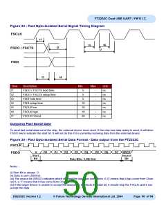
Figure 33 - Fast Opto-Isolated Serial Signal Timing Diagram
FSCLK
t1
t5
t6
t2
FSDO / FSCTS
FSDI
t7
t3
t4
Time
t1
Description
Min
Max
Unit
ns
ns
ns
ns
ns
ns
ns
FSDO / FSCTS hold time
FSDO / FSCTS setup time
FSDI hold time
5
-
-
-
-
-
-
-
t2
5
t3
5
t4
FSDI setup time
FSCLK low
10
10
10
20
t5
t6
FSCLK high
t7
FSCLK Period
Outgoing Fast Serial Data
To send fast serial data out of the chip, the external device must clock. If the chip has data ready to send, it will drive
FSDO low to indicate the start bit. It will not do this if it is currently receiving data from the external device.
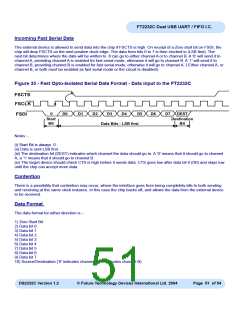
Figure 34 - Fast Opto-Isolated Serial Data Format - Data output from the FT2232C
FSCLK
0
Start
Bit
D0
D1
D2
D3
D4
D5
D6
D7
SRCE
Source
Bit
FSDO
Data Bits - LSB first
Notes :-
(i) Start Bit is always 0.
(ii) Data is sent LSB first.
(iii) The source bit (SRCE) indicates which channel the data has come from. A ‘0’ means that it has come from Chan-
nel A, a ‘1’ means that it has come from Channel B.
(iv) If the target device is unable to accept the data when it detects the start bit, it should stop the FSCLK until it can
accept the data.
DS2232C Version 1.2
© Future Technology Devices International Ltd. 2004
Page 50 of 54

 FTDI [ FUTURE TECHNOLOGY DEVICES INTERNATIONAL LTD. ]