FT2232C Dual USB UART / FIFO I.C.
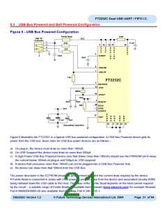
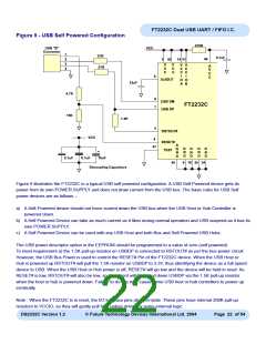
Figure 9 - USB Self Powered Configuration
470R
USB "B"
VCC
Connector
1
27R
0.1uF
46
2
3
3
42
14 31
V
C
C
V
C
C
V
C
C
I
V
A
V
C
C
27R
4
C
C
I
6
3v3OUT
O
A
O
B
33nF
4.7K
10K
8
7
USB DM
USB DP
FT2232C
1.5K
5
RSTOUT#
RESET#
VCC
4
A
47
G
N
D
G
N
D
G
N
D
G
N
D
G
N
D
TEST
+
0.1uF
0.1uF
10uF
45
9 18 25 34
Decoupling Capacitors
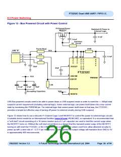
Figure 9 illustrates the FT2232C in a typical USB self powered configuration. A USB Self Powered device gets its
power from its own POWER SUPPLY and does not draw current from the USB bus. The basic rules for USB Self
power devices are as follows –
a) A Self-Powered device should not force current down the USB bus when the USB Host or Hub Controller is
powered down.
b) A Self Powered Device can take as much current as it likes during normal operation and USB suspend as it has its
own POWER SUPPLY.
c) A Self Powered Device can be used with any USB Host and both Bus and Self Powered USB Hubs.
The USB power descriptor option in the EEPROM should be programmed to a value of zero (self powered).
To meet requirement a) the 1.5K pull-up resistor on USBDP is connected to RSTOUT# as per the bus-power circuit.
However, the USB Bus Power is used to control the RESET# Pin of the FT2232C device. When the USB Host or
Hub is powered up RSTOUT# will pull the 1.5K resistor on USBDP to 3.3V, thus identifying the device as a full speed
device to USB. When the USB Host or Hub power is off, RESET# will go low and the device will be held in reset. As
RESET# is low, RSTOUT# will also be low, so no current will be forced down USBDP via the 1.5K pull-up resistor
when the host or hub is powered down. Failure to do this may cause some USB host or hub controllers to power up
erratically.
Note : When the FT2232C is in reset, the I/O interface pins all go tri-state. These pins have internal 200K pull-up
resistors to VCCIO, so they will gently pull high unless driven by some external logic.
DS2232C Version 1.2
© Future Technology Devices International Ltd. 2004
Page 22 of 54

 FTDI [ FUTURE TECHNOLOGY DEVICES INTERNATIONAL LTD. ]