FT2232C Dual USB UART / FIFO I.C.
8.3 USB Bus Powered and Self Powered Configuration
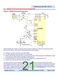
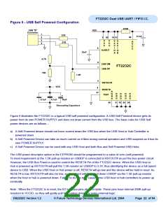
Figure 8 - USB Bus Powered Configuration
Ferrite Bead
470R
USB "B"
Connector
VCC
1
27R
0.1uF
2
3
3
42
14 31
46
V
C
C
V
C
C
A
V
C
C
V
C
C
I
V
27R
4
C
C
I
6
5
10nF
3v3OUT
O
A
O
A
33nF
8
7
USB DM
USB DP
1.5K
FT2232C
RSTOUT#
5
43
XTIN
6MHz
44
XTOUT
VCC
4
27pF
10K
27pF
RESET#
48
EECS
1
2
EESK
VCC
EEDATA
A
G
N
D
47
G
N
D
G
N
D
G
N
D
G
N
D
+
TEST
0.1uF
0.1uF
10uF
45
9
18 25 34
Decoupling Capacitors
Figure 8 illustrates the FT2232C in a typical USB bus powered configuration. A USB Bus Powered device gets its
power from the USB bus. Basic rules for USB Bus power devices are as follows –
a) On plug-in, the device must draw no more than 100mA
b) On USB Suspend the device must draw no more than 500μA.
c) A High Power USB Bus Powered Device (one that draws more than 100mA) should use the PWREN# pin to keep
the current below 100mA on plug-in and 500μA on USB suspend.
d) A device that consumes more than 100mA can not be plugged into a USB Bus Powered Hub
e) No device can draw more that 500mA from the USB Bus.
The power descriptor in the EEPROM should be programmed to match the current draw required by the device.
A Ferrite Bead is connected in series with USB power to prevent noise from the device and associated circuitry (EMI)
being radiated down the USB cable to the Host. The value of the Ferrite Bead depends on the total current required
by the circuit – a suitable range of Ferrite Beads is available from Steward (www.steward.com) for example Steward
Part # MI0805K400R-00 also available from DigiKey, Part # 240-1035-1.
DS2232C Version 1.2
© Future Technology Devices International Ltd. 2004
Page 21 of 54

 FTDI [ FUTURE TECHNOLOGY DEVICES INTERNATIONAL LTD. ]