FT2232C Dual USB UART / FIFO I.C.
8.5 Power Switching
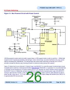
Figure 12 - Bus Powered Circuit with Power Control
P-Channel Power
MOSFET
Switched 5V Power to
External Logic
s
d
0.1uF
g
0.1uF
Soft Start
Circuit
1K
Ferrite Bead
27R
470R
USB "B"
Connector
VCC
1
2
3
4
0.1uF
46
3
42 14 31
V
C
C
V
C
C
V
C
C
I
V
C
C
I
A
27R
V
C
C
6
10nF
3V3OUT
O
A
O
B
33nF
FT2232C
8
7
USB DM
USB DP
VCC
41
PWREN#
+
1.5K
0.1uF
0.1uF
10uF
5
4
RSTOUT#
RESET#
Decoupling Capacitors
VCC
USB Bus powered circuits need to be able to power down in USB suspend mode in order to meet the <= 500μA total
suspend current requirement (including external logic). Some external logic can power itself down into a low current
state by monitoring the PWREN# pin. For external logic that cannot power itself down in that way, the FT2232C
provides a simple but effective way of turning off power to external circuitry during USB suspend.
Figure 12 shows how to use a discrete P-Channel Logic Level MOSFET to control the power to external logic circuits.
A suitable device would be an International Rectifier (www.irf.com) IRLML6402, or equivalent. It is recommended that
a “soft start” circuit consisting of a 1K series resistor and a 0.1 μF capacitor are used to limit the current surge when
the MOSFET turns on. Without the soft start circuit there is a danger that the transient power surge of the MOSFET
turning on will reset the FT2232C, or the USB host / hub controller. The values used here allow attached circuitry to
power up with a slew rate of ~12.5 V per millisecond, in other words the output voltage will transition from GND to 5V
in approximately 400 microseconds.
DS2232C Version 1.2
© Future Technology Devices International Ltd. 2004
Page 26 of 54

 FTDI [ FUTURE TECHNOLOGY DEVICES INTERNATIONAL LTD. ]