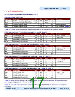
FT2232C Dual USB UART / FIFO I.C.
8.2 EEPROM Configuration
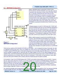
Figure 7 illustrates how to connect the FT2232C to the
93C46 (93C56 or 93C66) EEPROM. EECS (pin 48) is directly
connected to the chip select (CS) pin of the EEPROM. EESK
(pin 1) is directly connected to the clock (SK) pin of the
EEPROM. EEDATA (pin 2) is directly connected to the Data
In (Din) pin of the EEPROM. There is a potential condition
whereby both the Data Output (Dout) of the EEPROM can drive
out at the same time as the EEDATA pin of the FT2232C. To
prevent potential data clash in this situation, the Dout of the
EEPROM is connected to EEDATA of the FT2232C via a 2.2K
resistor.
FT2232C
48
1
EECS
EESK
2
EEDATA
VCC
EEPROM - 93C46 / 56 / 66
Following a power-on reset or a USB reset, the FT2232C will
scan the EEPROM to find out (a) if an EEPROM is attached to
the Device and (b) if the data in the device is valid. If both of
these are the case, then the FT2232C will use the data in the
EEPROM, otherwise it will use its built-in default values and
configuration. The default port configuration of the FT2232C
puts both Channel A and Channel B into serial UART mode.
1
8
7
6
5
CS
VCC
NC
2
3
SK
2.2K
DIN
DOUT
NC
4
GND
When a valid command is issued to the EEPROM from the
FT2232C, the EEPROM will acknowledge the command by
pulling its Dout pin low. In order to check for this condition,
it is necessary to pull Dout high using a 10K resistor. If the
command acknowledge doesn’t happen then EEDATA will be
pulled high by the 10K resistor during this part of the cycle
and the device will detect an invalid command or no EEPROM
present.
VCC
10K
Figure 7
EEPROM Configuration
There are two varieties of 93C46/56/66 EEPROM’s on the market – one is configured as being 16 bits wide, the other
is configured as being 8 bits wide. These are available from many sources such as Microchip, STMicro, ISSI etc. The
FT2232C requires EEPROM’s with a 16-bit wide configuration such as the Microchip 93LC46B device. The EEPROM
must be capable of reading data at a 1Mb clock rate at a supply voltage of 4.35V to 5.25V. Most available parts are
capable of this. Check the manufacturers data sheet to find out how to connect pins 6 and 7 of the EEPROM. Some
devices specify these as no-connect, others use them for selecting 8 / 16 bit mode or for test functions. Some other
parts have their pinout rotated by 90o so please select the required part and its options carefully.
It is possible to “share” the EEPROM between the FT2232C and another external device such as an MCU. However,
this can only be done when the FT2232C is in its reset condition as it tri-states its EEPROM interface at that time. A
typical configuration would use four bits of an MCU IO Port. One bit would be used to hold the FT2232C reset (using
RESET#) on power-up, the other three would connect to the EECS, EESK and EEDATA pins of the FT2232C in
order to read / write data to the EEPROM at this time. Once the MCU has read / written the EEPROM, it would take
RESET# high to allow the FT2232C to configure itself and enumerate over USB.
The external EEPROM can be programmed over USB using utility software provided by FTDI. The external EEPROM
is used to enable 245 FIFO, CPU-Style FIFO, and Fast Opto-Isolated Serial interface modes on each channel.
DS2232C Version 1.2
© Future Technology Devices International Ltd. 2004
Page 20 of 54

 FTDI [ FUTURE TECHNOLOGY DEVICES INTERNATIONAL LTD. ]