Development Support
Break Module (BRK)
18.2.1.1 Flag Protection During Break Interrupts
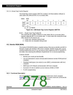
The BCFE bit in the SIM break flag control register (SBFCR) enables software to
clear status bits during the break state.
18.2.1.2 CPU During Break Interrupts
The CPU starts a break interrupt by:
•
•
Loading the instruction register with the SWI instruction
Loading the program counter with $FFFC and $FFFD ($FEFC and $FEFD
in monitor mode)
The break interrupt begins after completion of the CPU instruction in progress. If
the break address register match occurs on the last cycle of a CPU instruction, the
break interrupt begins immediately.
18.2.1.3 TIM1 and TIM2 During Break Interrupts
A break interrupt stops the timer counters.
18.2.1.4 COP During Break Interrupts
The COP is disabled during a break interrupt when VTST is present on the RST pin.
18.2.2 Low-Power Modes
The WAIT and STOP instructions put the MCU in low power- consumption standby
modes.
18.2.2.1 Wait Mode
18.2.2.2 Stop Mode
If enabled, the break module is active in wait mode. In the break routine, the user
can subtract one from the return address on the stack if SBSW is set. Clear the BW
bit by writing logic 0 to it.
The break module is inactive in stop mode. The STOP instruction does not affect
break module register states.
18.2.3 Break Module Registers
These registers control and monitor operation of the break module:
•
•
•
•
•
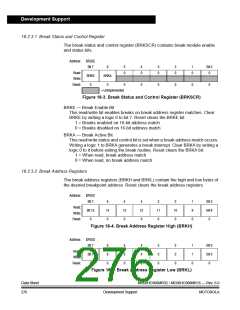
Break status and control register (BRKSCR)
Break address register high (BRKH)
Break address register low (BRKL)
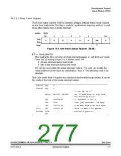
SIM break status register (SBSR)
SIM break flag control register (SBFCR)
MC68HC908MR32 • MC68HC908MR16 — Rev. 6.0
MOTOROLA
Data Sheet
275
Development Support

 FREESCALE [ Freescale ]