Timer Interface B (TIMB)
I/O Registers
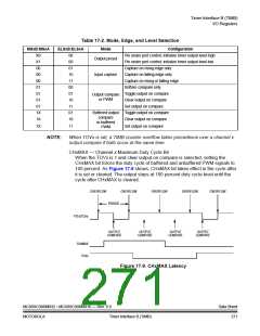
Table 17-2. Mode, Edge, and Level Selection
MSxB:MSxA
ELSxB:ELSxA
Mode
Configuration
Pin under port control; initialize timer output level high
X0
X1
00
00
00
01
01
01
01
1X
1X
00
00
01
10
11
00
01
10
11
01
10
Output preset
Pin under port control; initialize timer output level low
Capture on rising edge only
Capture on falling edge only
Capture on rising or falling edge
Softare compare only
Input capture
Toggle output on compare
Clear output on compare
Output compare
or PWM
Set output on compare
Buffered output
compare
or buffered
PWM
Toggle output on compare
Clear output on compare
1X
11
Set output on compare
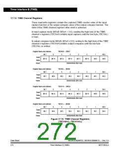
NOTE:
When TOVx is set, a TIMB counter overflow takes precedence over a channel x
output compare if both occur at the same time.
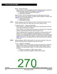
CHxMAX — Channel x Maximum Duty Cycle Bit
When the TOVx is 1 and clear output on compare is selected, setting the
CHxMAX bit forces the duty cycle of buffered and unbuffered PWM signals to
100 percent. As Figure 17-9 shows, CHxMAX bit takes effect in the cycle after
it is set or cleared. The output stays at 100 percent duty cycle level until the
cycle after CHxMAX is cleared.
OVERFLOW
OVERFLOW
OVERFLOW
OVERFLOW
OVERFLOW
PERIOD
PTEx/TCHx
OUTPUT
COMPARE
OUTPUT
COMPARE
OUTPUT
COMPARE
OUTPUT
COMPARE
CHxMAX
TOVx
Figure 17-9. CHxMAX Latency
MC68HC908MR32 • MC68HC908MR16 — Rev. 6.0
MOTOROLA
Data Sheet
271
Timer Interface B (TIMB)

 FREESCALE [ Freescale ]