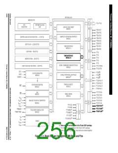
Timer Interface B (TIMB)
Functional Description
programmable. The level transition which triggers the counter transfer is defined by
the corresponding input edge bits (ELSxB and ELSxA in TBSC0–TBSC1 control
registers with x referring to the active channel number). When an active edge
occurs on the pin of an input capture channel, the TIMB latches the contents of the
TIMB counter into the TIMB channel registers, TCHxH–TCHxL. Input captures can
generate TIMB CPU interrupt requests. Software can determine that an input
capture event has occurred by enabling input capture interrupts or by polling the
status flag bit.
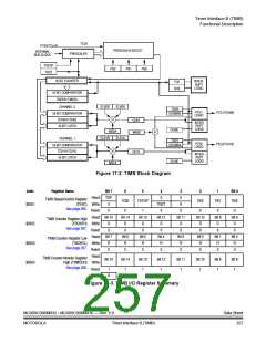
The free-running counter contents are transferred to the TIMB channel status and
control register (TBCHxH–TBCHxL, see 17.7.5 TIMB Channel Registers) on
each proper signal transition regardless of whether the TIMB channel flag
(CH0F–CH1F in TBSC0–TBSC1 registers) is set or clear. When the status flag is
set, a CPU interrupt is generated if enabled. The value of the count latched or
“captured” is the time of the event. Because this value is stored in the input capture
register two bus cycles after the actual event occurs, user software can respond to
this event at a later time and determine the actual time of the event. However, this
must be done prior to another input capture on the same pin; otherwise, the
previous time value will be lost.
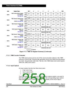
By recording the times for successive edges on an incoming signal, software can
determine the period and/or pulse width of the signal. To measure a period, two
successive edges of the same polarity are captured. To measure a pulse width, two
alternate polarity edges are captured. Software should track the overflows at the
16-bit module counter to extend its range.
Another use for the input capture function is to establish a time reference. In this
case, an input capture function is used in conjunction with an output compare
function. For example, to activate an output signal a specified number of clock
cycles after detecting an input event (edge), use the input capture function to
record the time at which the edge occurred. A number corresponding to the desired
delay is added to this captured value and stored to an output compare register (see
17.7.5 TIMB Channel Registers). Because both input captures and output
compares are referenced to the same 16-bit modulo counter, the delay can be
controlled to the resolution of the counter independent of software latencies.
Reset does not affect the contents of the input capture channel register
(TBCHxH–TBCHxL).
17.3.3 Output Compare
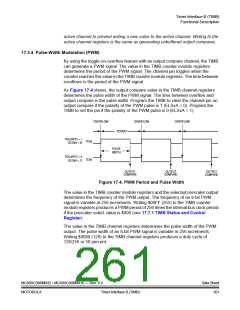
With the output compare function, the TIMB can generate a periodic pulse with a
programmable polarity, duration, and frequency. When the counter reaches the
value in the registers of an output compare channel, the TIMB can set, clear, or
toggle the channel pin. Output compares can generate TIMB CPU interrupt
requests.
MC68HC908MR32 • MC68HC908MR16 — Rev. 6.0
MOTOROLA Timer Interface B (TIMB)
Data Sheet
259

 FREESCALE [ Freescale ]