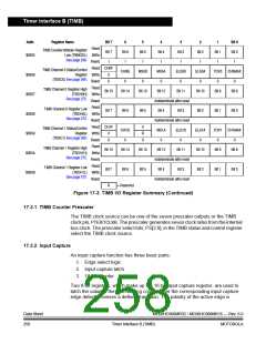
Timer Interface B (TIMB)
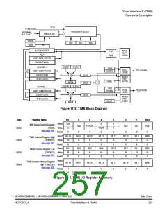
Addr.
Register Name
Bit 7
Bit 7
1
6
Bit 6
1
5
Bit 5
1
4
Bit 4
1
3
Bit 3
1
2
Bit 2
1
1
Bit 1
1
Bit 0
Bit 0
1
Read:
TIMB Counter Modulo Register
$0055
Low (TBMODL) Write:
See page 268.
Reset:
Read: CH0F
TIMB Channel 0 Status/Control
(TBSC0) See page 269.
CH0IE
0
MS0B
0
MS0A
0
ELS0B
0
ELS0A
0
TOV0 CH0MAX
$0056
$0057
$0058
$0059
$005A
$005B
Register Write:
0
0
Reset:
Read:
0
0
TIMB Channel 0 Register High
Bit 15
Bit 14
Bit 13
Bit 12
Bit 11
Bit 10
Bit 9
Bit 8
(TBCH0H) Write:
See page 272.
Reset:
Read:
Indeterminate after reset
Bit 4 Bit 3
Indeterminate after reset
TIMB Channel 0 Register Low
Bit 7
Bit 6
Bit 5
Bit 2
Bit 1
Bit 0
(TBCH0L) Write:
See page 272.
Reset:
Read: CH1F
0
R
0
TIMB Channel 1 Status/Control
(TBSC1) See page 269.
CH1IE
0
MS1A
0
ELS1B
0
ELS1A
0
TOV1 CH1MAX
Register Write:
0
0
Reset:
Read:
0
0
TIMB Channel 1 Register High
Bit 15
Bit 14
Bit 13
Bit 12
Bit 11
Bit 10
Bit 9
Bit 8
(TBCH1H) Write:
See page 272.
Reset:
Read:
Indeterminate after reset
Bit 4 Bit 3
Indeterminate after reset
TIMB Channel 1 Register Low
Bit 7
R
Bit 6
Bit 5
Bit 2
Bit 1
Bit 0
(TBCH1L) Write:
See page 272.
Reset:
= Reserved
Figure 17-3. TIMB I/O Register Summary (Continued)
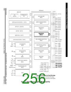
17.3.1 TIMB Counter Prescaler
The TIMB clock source can be one of the seven prescaler outputs or the TIMB
clock pin, PTE0/TCLKB. The prescaler generates seven clock rates from the internal
bus clock. The prescaler select bits, PS[2:0], in the TIMB status and control register
select the TIMB clock source.
17.3.2 Input Capture
An input capture function has three basic parts:
1. Edge select logic
2. Input capture latch
3. 16-bit counter
Two 8-bit registers, which make up the 16-bit input capture register, are used to
latch the value of the free-running counter after the corresponding input capture
edge detector senses a defined transition. The polarity of the active edge is
Data Sheet
258
MC68HC908MR32 • MC68HC908MR16 — Rev. 6.0
Timer Interface B (TIMB)
MOTOROLA

 FREESCALE [ Freescale ]