Timer Interface A (TIMA)
I/O Registers
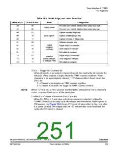
Table 16-2. Mode, Edge, and Level Selection
MSxB:MSxA
ELSxB:ELSxA
Mode
Configuration
Pin under port control; initialize timer output level high
X0
X1
00
00
00
01
01
01
01
1X
1X
1X
00
00
01
10
11
00
01
10
11
01
10
11
Output preset
Pin under port control; initialize timer output level low
Capture on rising edge only
Capture on falling edge only
Capture on rising or falling edge
Software compare only
Input capture
Output
compare
or PWM
Toggle output on compare
Clear output on compare
Set output on compare
Toggle output on compare
Clear output on compare
Buffered
output compare
or buffered PWM
Set output on compare
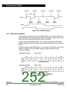
TOVx — Toggle-On-Overflow Bit
When channel x is an output compare channel, this read/write bit controls the
behavior of the channel x output when the TIMA counter overflows. When
channel x is an input capture channel, TOVx has no effect. Reset clears the
TOVx bit.
1 = Channel x pin toggles on TIMA counter overflow.
0 = Channel x pin does not toggle on TIMA counter overflow.
NOTE:
When TOVx is set, a TIMA counter overflow takes precedence over a channel x
output compare if both occur at the same time.
CHxMAX — Channel x Maximum Duty Cycle Bit
When the TOVx is 1 and clear output on compare is selected, setting the
CHxMAX bit forces the duty cycle of buffered and unbuffered PWM signals to
100 percent. As Figure 16-9 shows, CHxMAX bit takes effect in the cycle after
it is set or cleared. The output stays at 100 percent duty cycle level until the
cycle after CHxMAX is cleared.
MC68HC908MR32 • MC68HC908MR16 — Rev. 6.0
MOTOROLA
Data Sheet
251
Timer Interface A (TIMA)

 FREESCALE [ Freescale ]