Serial Peripheral Interface Module (SPI)
Error Conditions
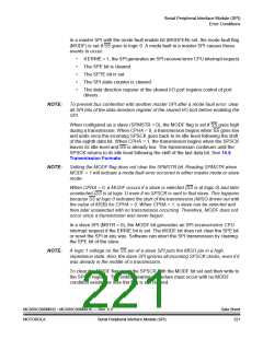
SPSCK CYCLE #
FOR REFERENCE
1
2
3
4
5
6
7
8
SPSCK, CPOL = 0
SPSCK, CPOL = 1
MOSI
FROM MASTER
MSB
MSB
BIT 6
BIT 6
BIT 5
BIT 5
BIT 4
BIT 4
BIT 3
BIT 3
BIT 2
BIT 2
BIT 1
BIT 1
LSB
MISO
FROM SLAVE
LSB
SS, TO SLAVE
CAPTURE STROBE
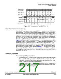
Figure 15-7. Transmission Format (CPHA = 1)
15.5.4 Transmission Initiation Latency
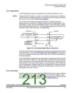
When the SPI is configured as a master (SPMSTR = 1), writing to the SPDR starts
a transmission. CPHA has no effect on the delay to the start of the transmission,
but it does affect the initial state of the SPSCK signal. When CPHA = 0, the SPSCK
signal remains inactive for the first half of the first SPSCK cycle. When CPHA = 1,
the first SPSCK cycle begins with an edge on the SPSCK line from its inactive to
its active level. The SPI clock rate (selected by SPR1:SPR0) affects the delay from
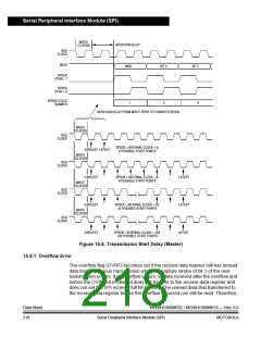
the write to SPDR and the start of the SPI transmission. See
Figure 15-8 The internal SPI clock in the master is a free-running derivative of the
internal MCU clock. To conserve power, it is enabled only when both the SPE and
SPMSTR bits are set. SPSCK edges occur halfway through the low time of the
internal MCU clock. Since the SPI clock is free-running, it is uncertain where the
write to the SPDR occurs relative to the slower SPSCK. This uncertainty causes
the variation in the initiation delay shown in Figure 15-8. This delay is no longer
than a single SPI bit time. That is, the maximum delay is two MCU bus cycles for
DIV2, eight MCU bus cycles for DIV8, 32 MCU bus cycles for DIV32, and 128 MCU
bus cycles for DIV128.
15.6 Error Conditions
These flags signal SPI error conditions:
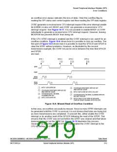
•
Overflow (OVRF) — Failing to read the SPI data register before the next full
byte enters the shift register sets the OVRF bit. The new byte does not
transfer to the receive data register, and the unread byte still can be read.
OVRF is in the SPI status and control register.
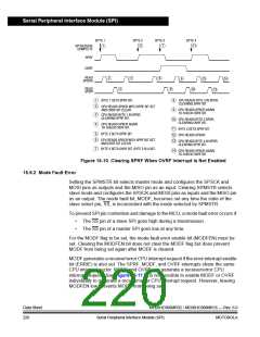
•
Mode fault error (MODF) — The MODF bit indicates that the voltage on the
slave select pin (SS) is inconsistent with the mode of the SPI. MODF is in
the SPI status and control register.
MC68HC908MR32 • MC68HC908MR16 — Rev. 6.0
MOTOROLA Serial Peripheral Interface Module (SPI)
Data Sheet
217

 FREESCALE [ Freescale ]