Serial Peripheral Interface Module (SPI)
WRITE
TO SPDR
INITIATION DELAY
BUS
CLOCK
MOSI
MSB
BIT 6
BIT 5
SPSCK
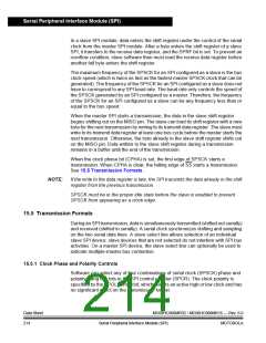
CPHA = 1
SPSCK
CPHA = 0
SPSCK CYCLE
NUMBER
1
2
3
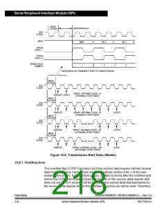
INITIATION DELAY FROM WRITE SPDR TO TRANSFER BEGIN
WRITE
TO SPDR
BUS
CLOCK
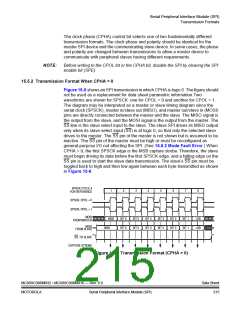
SPSCK = INTERNAL CLOCK ÷ 2;
2 POSSIBLE START POINTS
EARLIEST LATEST
WRITE
TO SPDR
BUS
CLOCK
EARLIEST
WRITE
TO SPDR
SPSCK = INTERNAL CLOCK ÷ 8;
8 POSSIBLE START POINTS
LATEST
LATEST
LATEST
BUS
CLOCK
EARLIEST
WRITE
TO SPDR
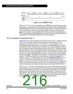
SPSCK = INTERNAL CLOCK ÷ 32;
32 POSSIBLE START POINTS
BUS
CLOCK
EARLIEST
SPSCK = INTERNAL CLOCK ÷ 128;
128 POSSIBLE START POINTS
Figure 15-8. Transmission Start Delay (Master)
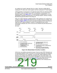
15.6.1 Overflow Error
The overflow flag (OVRF) becomes set if the receive data register still has unread
data from a previous transmission when the capture strobe of bit 1 of the next
transmission occurs. If an overflow occurs, all data received after the overflow and
before the OVRF bit is cleared does not transfer to the receive data register and
does not set the SPI receiver full bit (SPRF). The unread data that transferred to
the receive data register before the overflow occurred can still be read. Therefore,
Data Sheet
218
MC68HC908MR32 • MC68HC908MR16 — Rev. 6.0
Serial Peripheral Interface Module (SPI)
MOTOROLA

 FREESCALE [ Freescale ]